Roller for plating

A roller and cylindrical technology, applied in the field of electroplating rollers, can solve the problems of size limitation, increase manufacturing cost, lack of versatility, etc., and achieve the effects of preventing catching or falling off, reducing manufacturing cost and improving versatility

Active Publication Date: 2007-08-15
KIDA SEIKO
View PDF2 Cites 7 Cited by
  • Summary
  • Abstract
  • Description
  • Claims
  • Application Information

AI Technical Summary

Problems solved by technology

That is, there is a problem that the life of the drum is short and the running cost is high
[0009] On the other hand, in a drum formed by alternately stacking a plurality of frame plates and pads formed into a horseshoe shape, the number of parts required for assembly increases and is troublesome, so there is a problem that the manufacturing cost increases.
[0010] In addition, since the spacers arranged in the circumferential direction of the drum are relatively wide and arc-shaped, if the parts to be plated are too small, they will be caught due to stagnation, and even the parts to be plated will fall off the drum. problems (i.e. limitations in size of parts to be plated, lack of versatility)

Method used


Image

  • Roller for plating
  • Roller for plating
  • Roller for plating

Examples


Embodiment Construction

[0032] Hereinafter, embodiments of the present invention will be described with reference to the drawings.

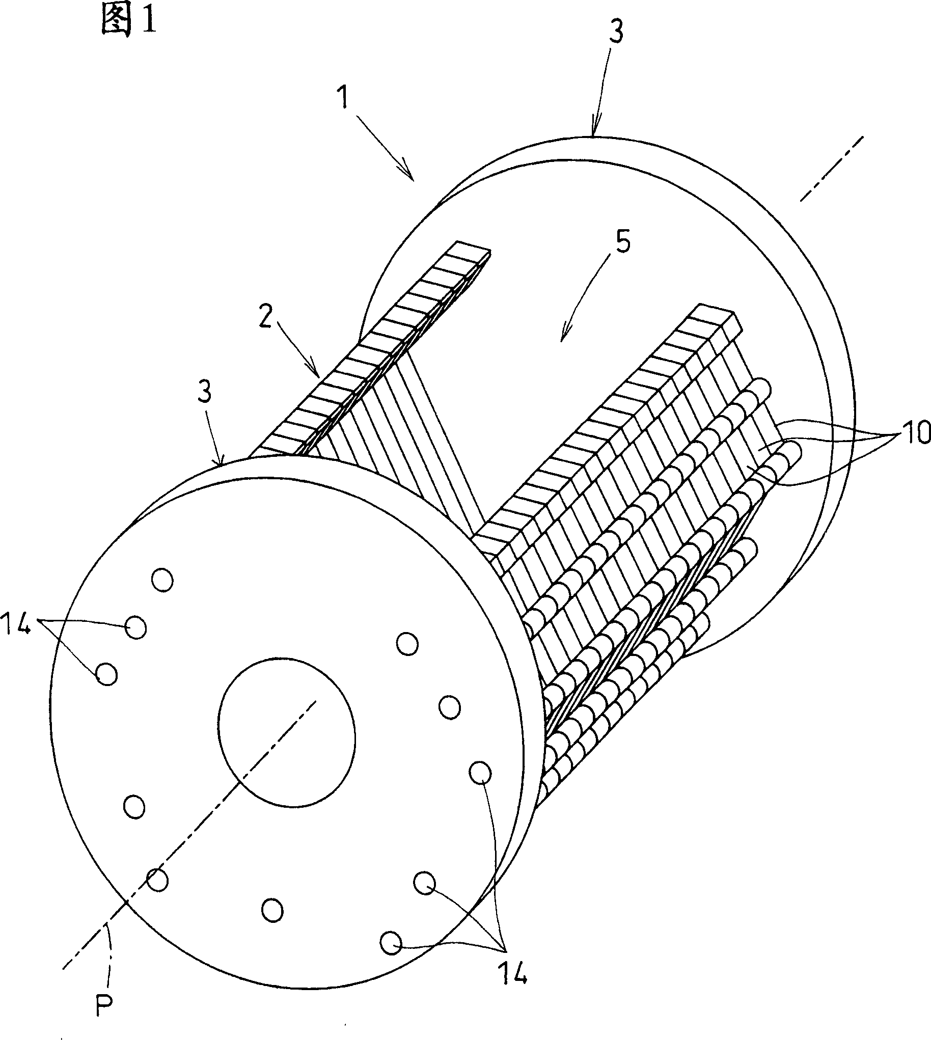
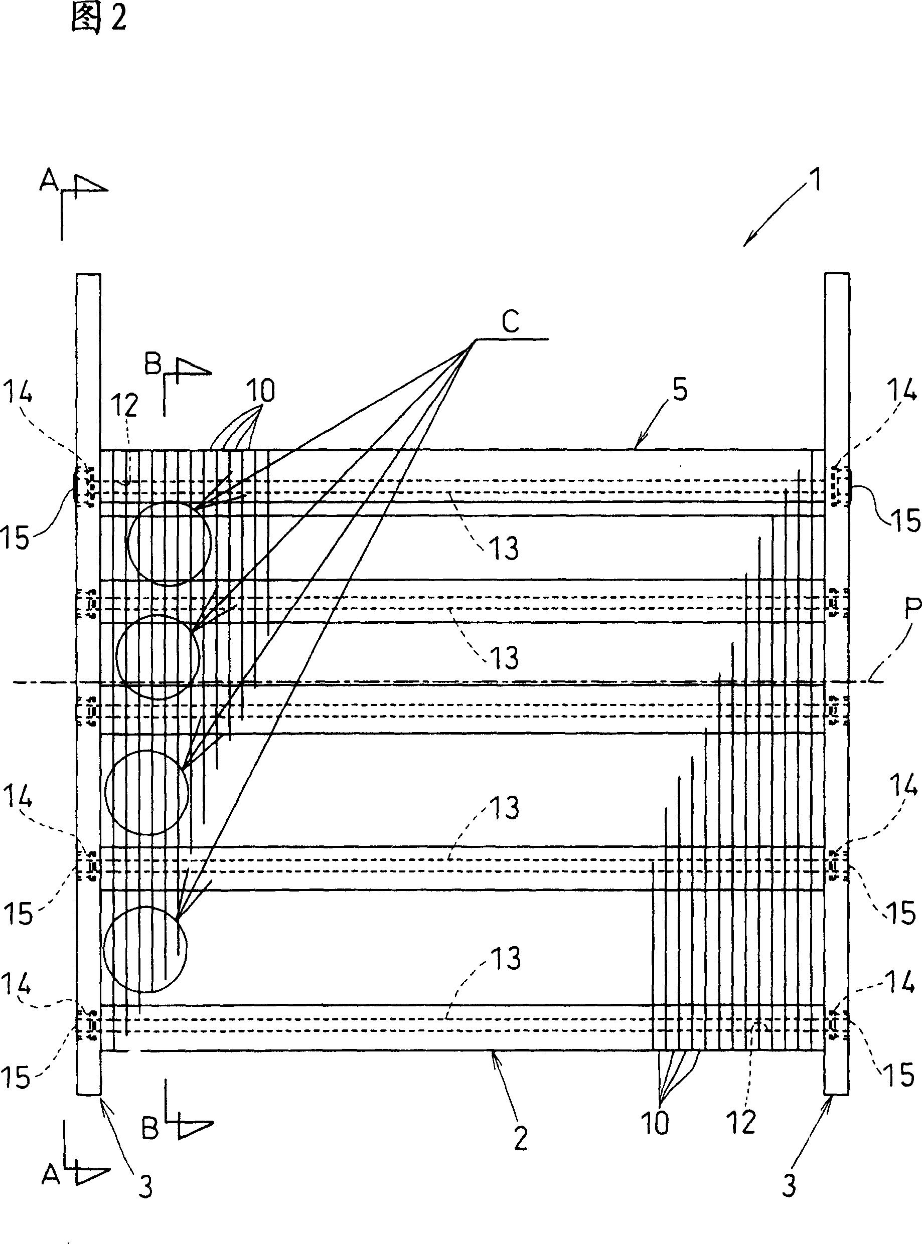
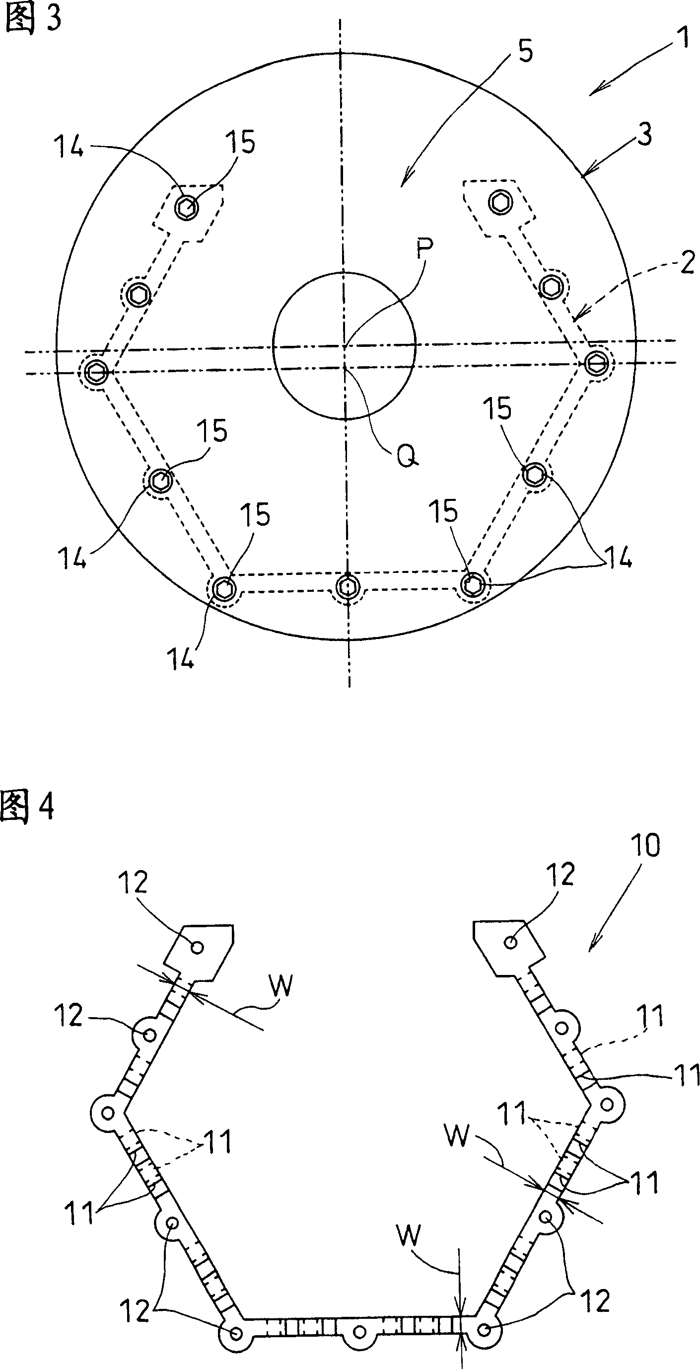
[0033] 1 to 5 show a first embodiment of a plating drum 1 of the present invention. This drum 1 has a main body 2 and end walls 3 provided at both ends of the main body 2, the main body 2 is formed in a cylindrical shape with both ends open, and the end walls 3 are in a state of closing both ends of the main body 2. Combined with this main body part 2.

[0034] In this embodiment, the main body portion 2 is formed into a hollow regular hexagonal square tube in cross-section, and the workpiece to be plated is placed here in a state where one side (a side surface imitating a regular hexagon) is removed. Port 5.

[0035] The workpiece to be plated can be accommodated or taken out from the cavity formed inside the main body 2 (the range surrounding both ends by the end wall 3 ) through the workpiece opening 5 . During plating, a resin cover (not shown) is attached to the...


PUM


Abstract

An object of the present invention is to provide a cylinder for electroplating which can achieve a longer life against abrasion caused by contact with a workpiece to be plated and which can reduce manufacturing costs. The electroplating cylinder of the present invention is provided with a water-permeable cylindrical body portion (2) and end walls (3) arranged at both ends thereof. It is formed by directly overlapping and connecting multiple pieces along the rotation axis. The peripheral wall constituent material (10) is cut into a circular thin plate shape perpendicular to the rotation axis. On each peripheral wall constituent material (10), in order to Water-permeable holes are formed between the surrounding wall constituent materials (10) in overlapping relationship, and a recessed portion (11) is formed in the plate thickness direction.

Description

technical field [0001] This invention relates to electroplating drums for use in electroplating relatively small items. Background technique [0002] In the case of electroplating relatively small small parts represented by bolts, nuts, washers, electric parts, etc., the barrel plating method (Ha*rel Metsuki method) is generally used. In this drum plating method, the workpiece to be plated is put into a cage (herein referred to as a drum) having a hollow regular hexagonal cross-section, and the entire drum is immersed in the plating solution in a semi-submerged state. , the drum is rotated around the cylinder axis. In addition, a sheet-shaped power supply member or an electrode may be placed in the drum, and a cathodic current may be applied in a state where these members are in contact with the object to be plated. [0003] Such a roller is generally made of resin so that it is resistant to the plating solution and does not adhere to the plating solution. In addition, si...

Claims


Application Information

Patent Timeline
Patent Type & Authority Applications(China)
IPC IPC(8): C25D17/20
Inventor 木田贵文
Owner KIDA SEIKO
Why Eureka
Try Eureka