

A port convergence method and device
A port aggregation and port technology, which is applied in the network field and can solve problems such as long service interruption time.
- Summary
- Abstract
- Description
- Claims
- Application Information
AI Technical Summary
Problems solved by technology
Method used
Image

Examples
Embodiment 1
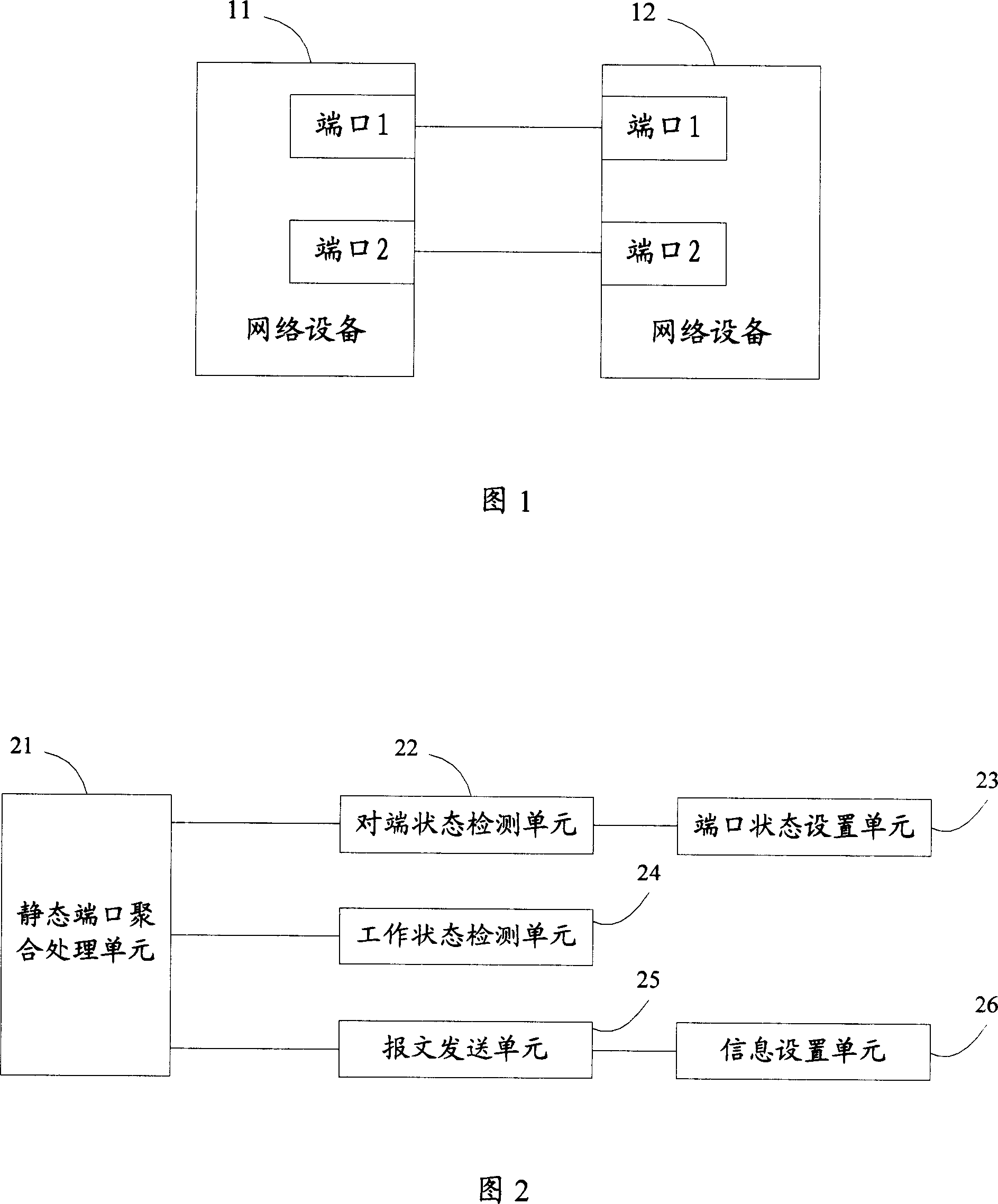
[0028] Embodiment 1, when the network device connection structure shown in FIG. 1 and the port aggregation device shown in FIG. 2 are adopted, the process of creating a static LAG in this embodiment is shown in FIG. 3 . In this embodiment, it is assumed that neither the network device 11 nor the network device 12 has created a static LAG. With reference to FIG. 3 , this embodiment includes the following steps:
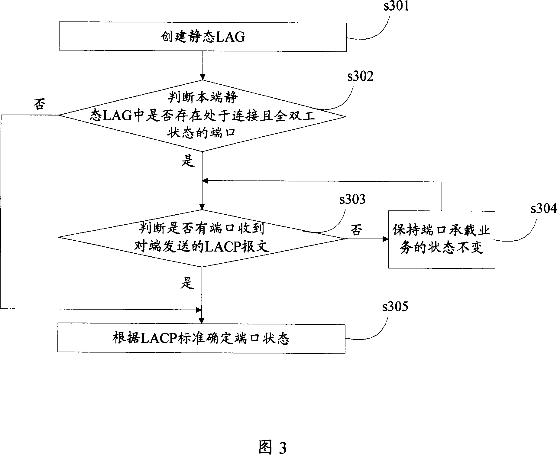
[0029] In step s301 , the static port aggregation processing unit 21 of the network device 11 creates a static LAG1 including port 1 and port 2 of the network device 11 .
[0030]In step s302, the peer state detection unit 22 of the network device 11 judges whether there is a port in the static LAG1 that is connected and full-duplex. If yes, go to step s303, otherwise go to step s305. In this embodiment, both port 1 and port 2 of the network device 11 are connected and in a full-duplex state, so go to step s303.
[0031] In step s303, the peer state detection unit 22 ...
Embodiment 2
[0034] Embodiment 2, when the network device connection structure shown in FIG. 1 and the port aggregation device shown in FIG. 2 are adopted, the process of deleting a static LAG in this embodiment is shown in FIG. 4 . In this embodiment, it is assumed that the network device 11 creates a static LAG1 including port 1 and port 2 of the network device 11 ; the network device 12 creates a static LAG2 including port 1 and port 2 of the network device 12 . Referring to Fig. 4, the process of deleting static LAG1 in this embodiment includes the following steps:
[0035] In step s401, the working state detection unit 24 of the network device 11 judges whether the port 1 and the port 2 of the network device 11 are in the working state. If yes, go to step s402, otherwise go to step s404. In this embodiment, the port 1 of the network device 11 is in the working state, and the port 2 is in the non-working state. Taking the processing of port 1 as an example, because port 1 is in worki...
Embodiment 3
[0040] Embodiment 3, when the network device connection structure shown in FIG. 1 and the port aggregation device shown in FIG. 2 are adopted, the flow of deleting member ports in this embodiment is shown in FIG. 5 . In this embodiment, it is assumed that the network device 11 creates a static LAG1 including port 1 and port 2 of the network device 11 ; the network device 12 creates a static LAG2 including port 1 and port 2 of the network device 12 . Referring to Fig. 4, the process of deleting the port 1 of the network device 11 in the present embodiment includes the following steps:
[0041] In step s501, the working state detection unit 24 of the network device 11 judges whether the port 1 of the network device 11 is in the working state. If yes, go to step s502, otherwise go to step s504. In this embodiment, the port 1 of the network device 11 is in the working state, so go to step s502.
[0042] In step s502, the information setting unit 26 of the network device 11 sets ...
PUM
 Abstract
Description
Claims
Application Information