Glass plate pressure defoaming machine

A pressurized defoaming and glass substrate technology, which is applied in the field of defoaming devices, can solve problems such as support mechanism breakage, achieve the effects of volume reduction, shortening process time, and avoiding uneven configuration

Inactive Publication Date: 2007-08-22
AU OPTRONICS CORP
View PDF0 Cites 4 Cited by
  • Summary
  • Abstract
  • Description
  • Claims
  • Application Information

AI Technical Summary

Problems solved by technology

The degassing device of the present invention can improve the efficiency of the degassing operation

Method used


Image

  • Glass plate pressure defoaming machine
  • Glass plate pressure defoaming machine
  • Glass plate pressure defoaming machine

Examples


Embodiment Construction

[0028] The invention relates to a degassing device for a glass substrate. The defoaming device of the present invention can improve the efficiency of the defoaming operation, and can solve related problems such as breakage of the support mechanism caused by the overweight cassette. A detailed description of the present invention is as follows.

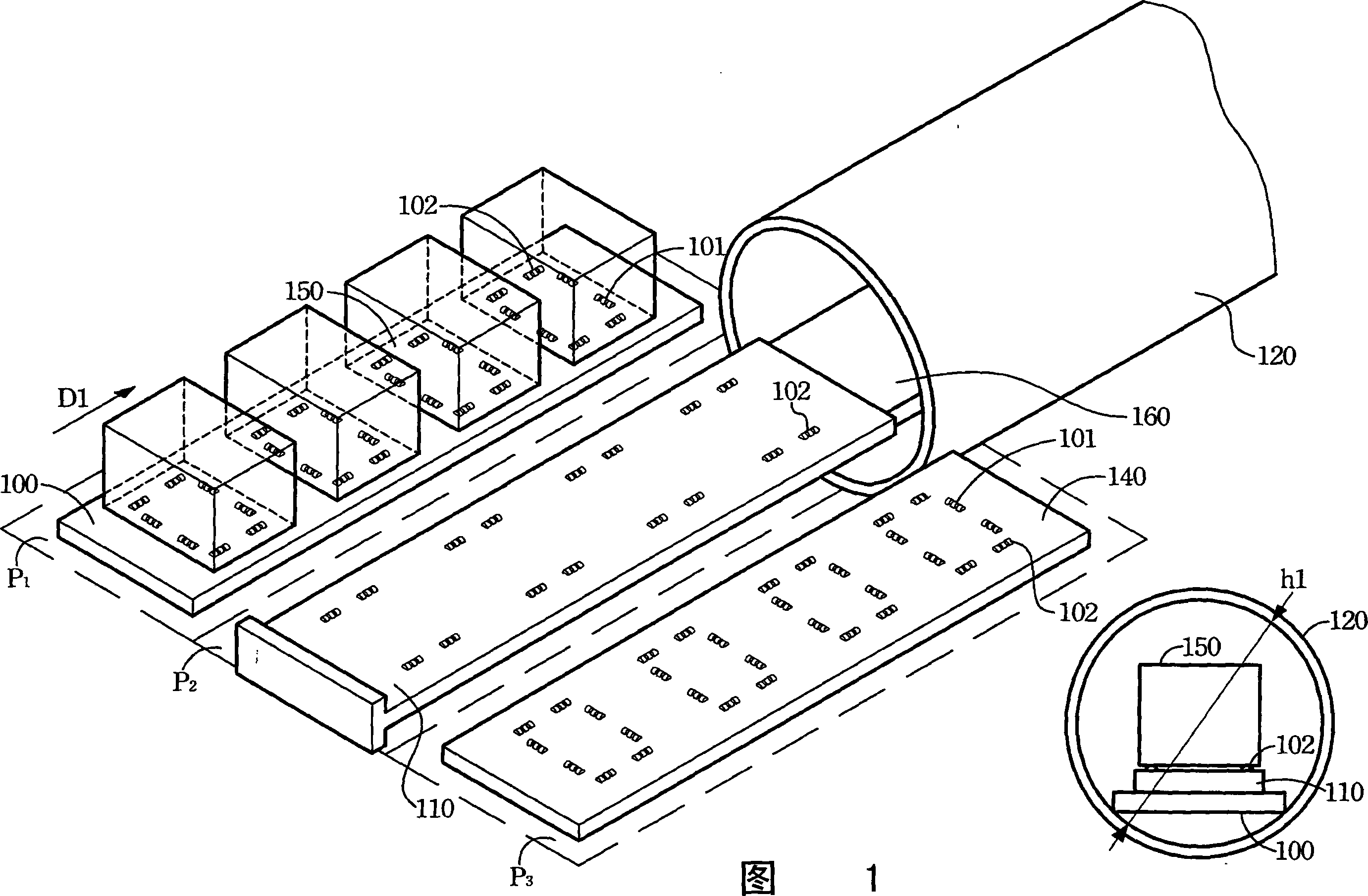
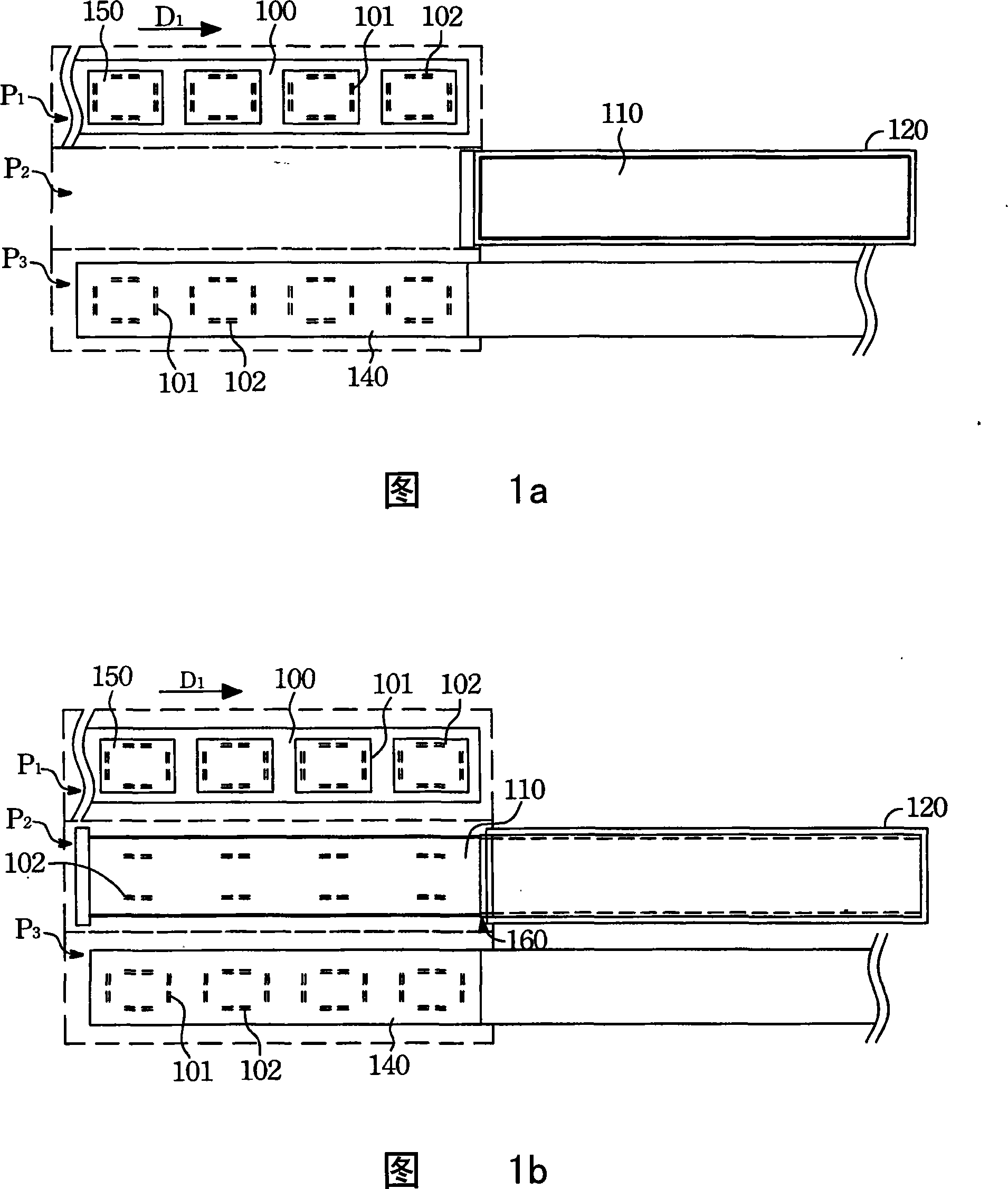
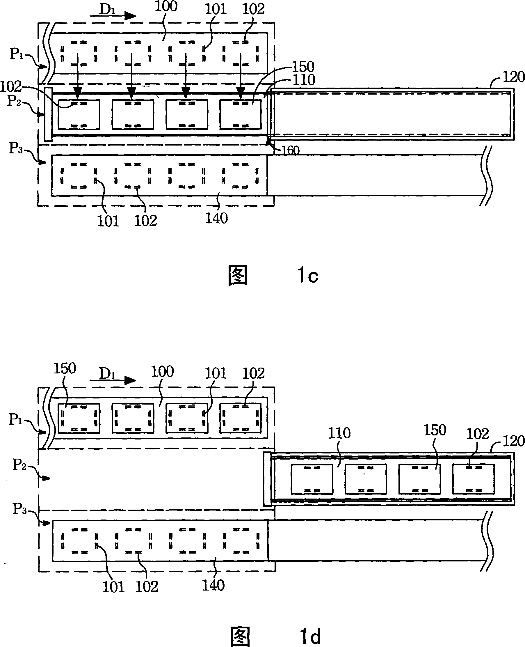
[0029] Please refer to FIG. 2 , which is an appearance view of the degassing device of the present invention. The degassing device of the present invention includes a degassing reaction furnace 220 , a loading platform 200 and an unloading platform 240 . The defoaming reaction furnace 220 has a furnace mouth, a slide table 210 is arranged inside the furnace mouth, and a furnace door 280 is arranged outside the furnace mouth. The sliding table 210 is provided with a plurality of first direction transmission wheels 201 . The carrying platform 200 reciprocates between the first position P1 and the second position P2, and the carrying p...


PUM


Abstract

The glass plate pressure defoaming machine for defoaming glass plates in some boxes includes one defoaming reaction furnace, one loading stage and one unloading stage. The defoaming reaction furnace has one fire hole and one sliding table inside the fire hole. When the loading stage is in its first position, several boxes may be loaded; and when it is moved to the second position, the boxes may be transferred to the sliding table of the defoaming reaction furnace for defoaming the glass plates. The boxes after defoaming may be unloaded with the unloading stage from the second position to the third position.

Description

【Technical field】 [0001] The invention relates to a degassing device for a glass substrate. 【Background technique】 [0002] With the advancement of science and technology, various information products such as mobile phones, notebook computers, digital cameras, PDAs, LCD screens and other products are becoming more and more popular, which greatly increases the demand for flat panel displays. In the glass substrate manufacturing process of flat-panel displays, the electronic components are placed on the glass substrate, and finally the optical film (such as a polarizer) is attached to the glass substrate. Among them, the process of attaching the optical film is easy to generate air bubbles. The existence of these air bubbles will affect the The quality of the LCD screen is affected, so the defoaming device plays a very important role in the glass substrate manufacturing process. Its main function is to remove bubbles by means of high pressure and high temperature. [0003] Pl...

Claims


Application Information

Patent Timeline
IPC IPC(8): C03C23/00
Inventor 萧俊斌
Owner AU OPTRONICS CORP
Why Eureka
Try Eureka