Cast-in-place concrete hollow core slab

A hollow slab, cast-in-place concrete technology, applied in the direction of floor slabs, building components, buildings, etc.

Inactive Publication Date: 2007-08-22
湖南邱则有专利战略策划有限公司
View PDF3 Cites 0 Cited by
  • Summary
  • Abstract
  • Description
  • Claims
  • Application Information

AI Technical Summary

Problems solved by technology

In this way, since the intersecting corners of at least two adjacent surfaces of the hollow carcass are at least one of arc angles, chamfers or inner corners, anti-collision tie bars are arranged in the legs, and are anchored to the legs and the outer wall at the same time. Therefore, it can effectively eliminate the stress concentration phenomenon at the corner of the hollow carcass in the hollow slab, prevent the generation of cracks, and can withstand large concentrated loads without damage, improving the mechanical properties of the hollow slab; at the same time, the supporting feet It has good integrity, high strength, high rigidity, an

Method used


Image

  • Cast-in-place concrete hollow core slab
  • Cast-in-place concrete hollow core slab
  • Cast-in-place concrete hollow core slab

Examples


Embodiment Construction

[0074] Below in conjunction with accompanying drawing and embodiment the present invention will be further described

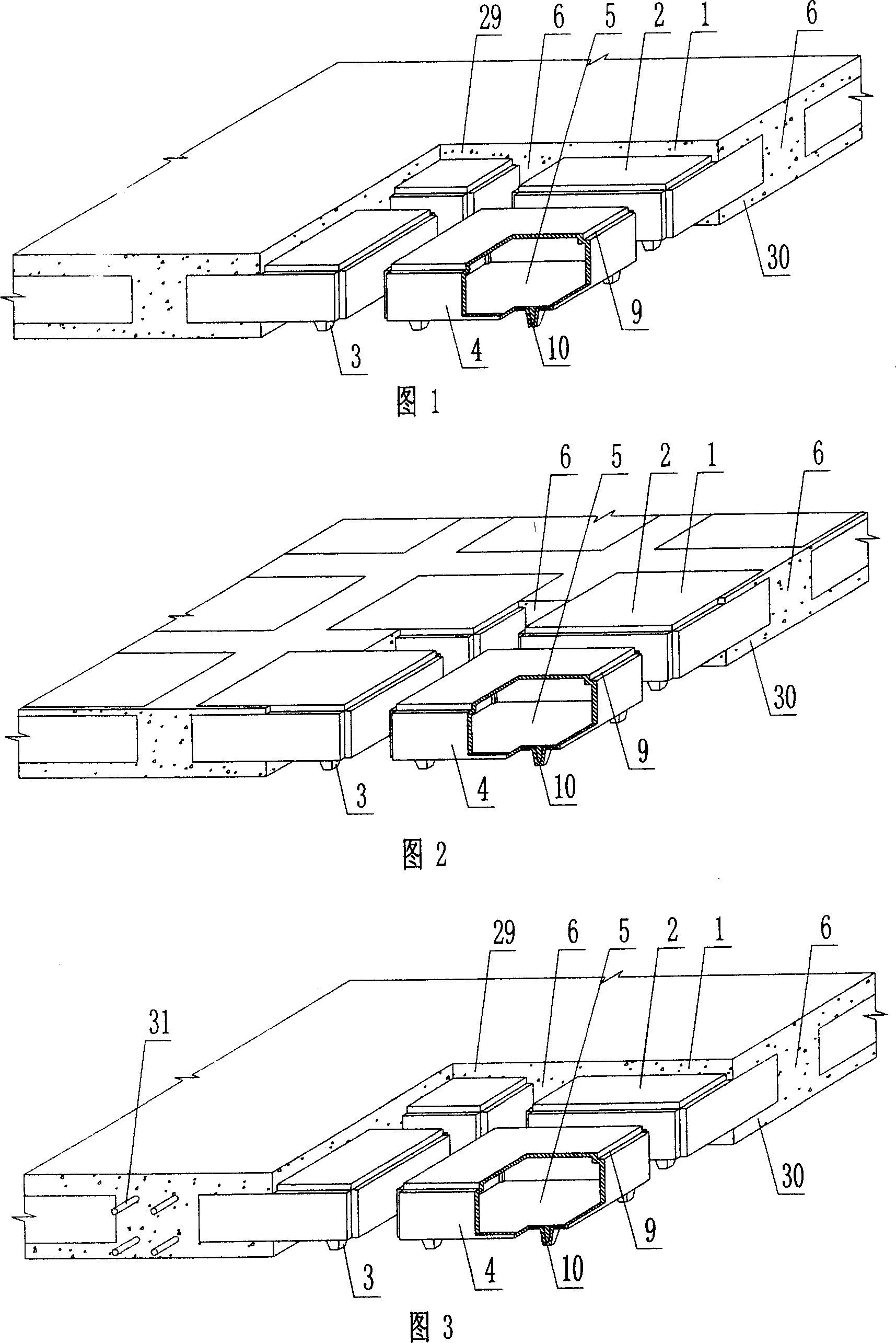
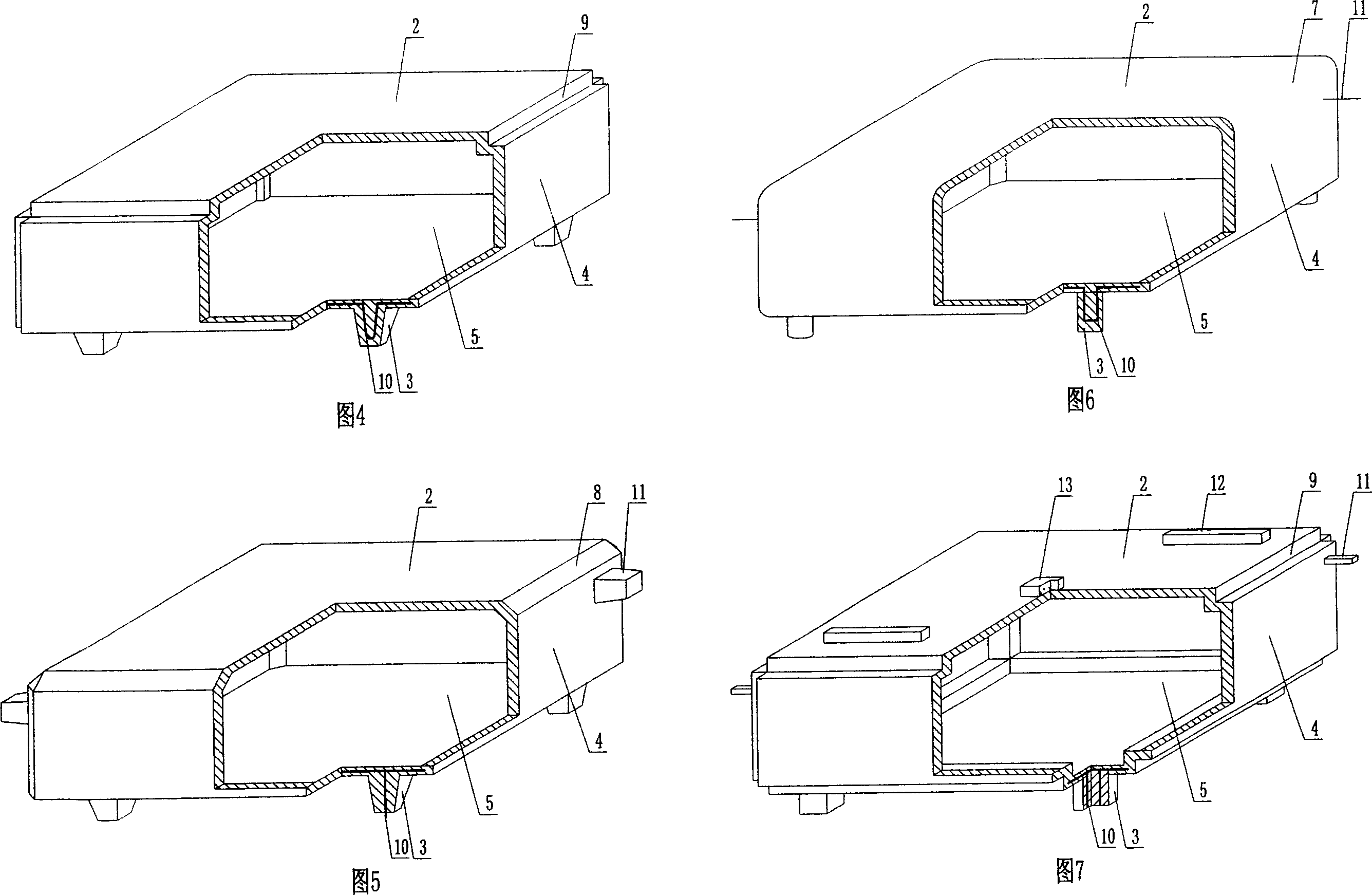
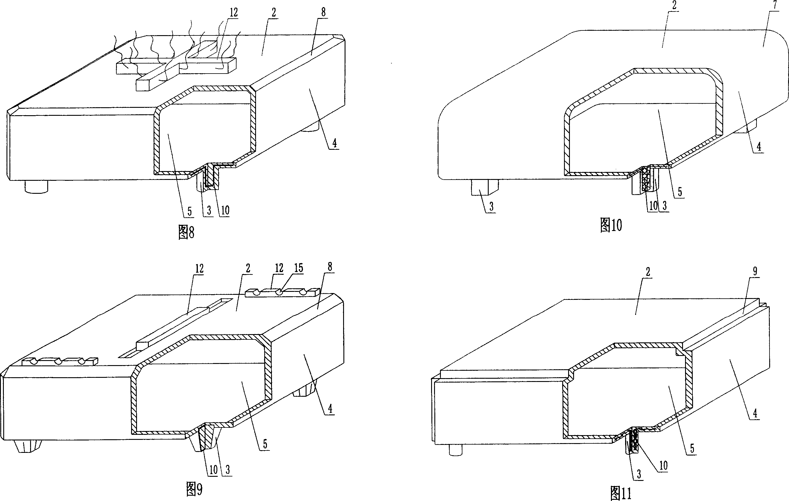
[0075] As shown in the accompanying drawings, the present invention includes a reinforced concrete 1 and a hollow carcass 2, the hollow carcass 2 is wrapped in the reinforced concrete 1, the bottom outer wall 4 of the hollow carcass 2 is provided with a support foot 3, and the outer wall 4 is enclosed to form A hollow carcass 2 with a cavity 5, and the cast-in-place reinforced concrete ribs 6 formed by the reinforced concrete 1 between the hollow carcass 2 are characterized in that the intersecting corners of at least two adjacent surfaces of the hollow carcass 2 It is at least one of the arc corner 7, the chamfer 8 or the inner corner 9, and the anti-collision tie rib 10 is arranged in the support foot 3, and is anchored in the support foot 3 and the outer wall 4 at the same time. In each attached drawing, 1 is reinforced concrete, 2 is hollow carcass, 3 is s...


PUM


Abstract

The present invention relates to a kind of in-situ concrete hollow slab. It includes reinforced concrete and hollow form bodies. The hollow form bodies are wrapped in the reinforced concrete, on the outer wall of hollow form body undersurface a supporting pin is set, said outer wall can be formed into the hollow form body with hollow cavity, between the adjacent hollow form bodies a cast-in-situ reinforced concrete rib is set. It is characterized by that the crossed corner of at least two adjacent faces of the described hollow form body is at least one kind of curved corner, chamfered corner or inside corner. Said invention is applicable to construction of in-situ reinforced concrete or prestressed reinforced concrete hollow floor, roof, wall body, foundation base plate and bridge, specially, it is applicable to construction of hollow beamless floor.

Description

(1) Technical field [0001] The invention relates to a cast-in-place concrete hollow slab. (2) Background technology [0002] At present, the cast-in-place concrete hollow floor is a widely used floor structure. The lightweight permanent tire molds filled in it include various hollow tubes and boxes, and the boxes are hollow or solid. For example, the patent No. ZL99249798.1, which the applicant applied for on November 29, 1999, is a utility model patent named "fiber-reinforced thin-walled member for reinforced concrete filling", which discloses a thin-walled formwork member, including an upper plate, The surrounding side walls, the lower bottom, and the upper plate, the surrounding side walls and the lower bottom form a polyhedral cavity. Another example is that the patent No. is ZL00203695.9, and the name is called "combined concrete hidden rib floor slab" utility model patent, which discloses a formwork member in its specification, which can be solid or hollow, and its sh...

Claims


Application Information

Patent Timeline
IPC IPC(8): E04B5/18E04B5/36
Inventor 邱则有
Owner 湖南邱则有专利战略策划有限公司
Why Eureka
Try Eureka