Optical fiber gyroscopic inertial measuring unit field calibrating method

A technology of inertial measurement unit and fiber optic gyroscope, which is applied in the direction of acceleration measurement, measurement device, speed/acceleration/shock measurement equipment testing/calibration by using gyroscope, which can solve the problem of low precision, increased experimental complexity, and inability to calibrate Problems such as gyroscope installation errors

Active Publication Date: 2007-08-22
BEIHANG UNIV
View PDF0 Cites 19 Cited by
  • Summary
  • Abstract
  • Description
  • Claims
  • Application Information

AI Technical Summary

Problems solved by technology

The two-position method is to rotate the IMU forward at a constant speed by 180°, and then rotate it in the reverse direction by 180° at a constant speed. Then, according to the simplified error model of the IMU, the scale factor of the IMU, the gyro constant value error and the accelerometer constant value bias are calibrated. There are 9 error coefficients, this method cannot calibrate the installation error of the gyroscope, and th

Method used


Image

  • Optical fiber gyroscopic inertial measuring unit field calibrating method
  • Optical fiber gyroscopic inertial measuring unit field calibrating method
  • Optical fiber gyroscopic inertial measuring unit field calibrating method

Examples


Embodiment Construction

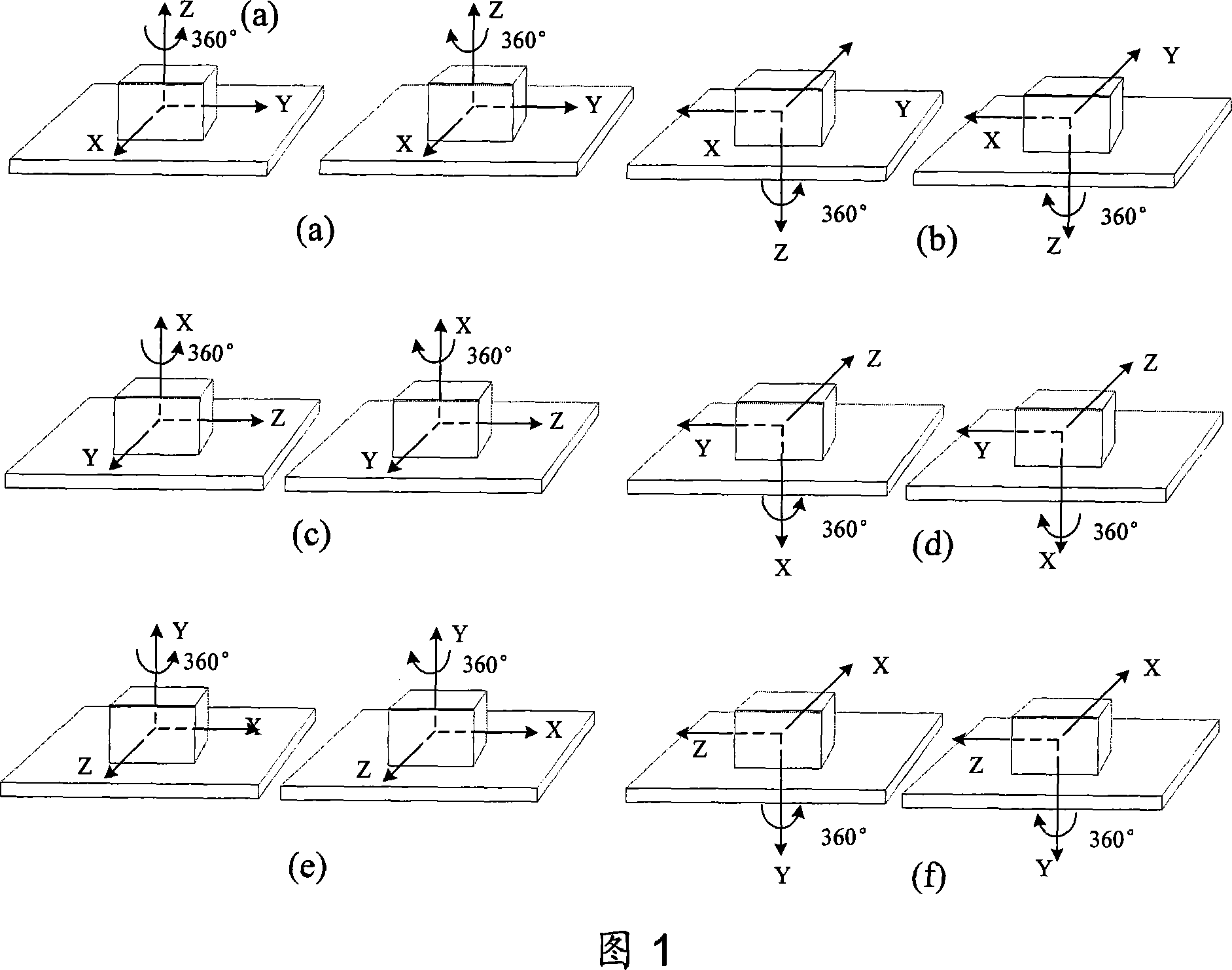
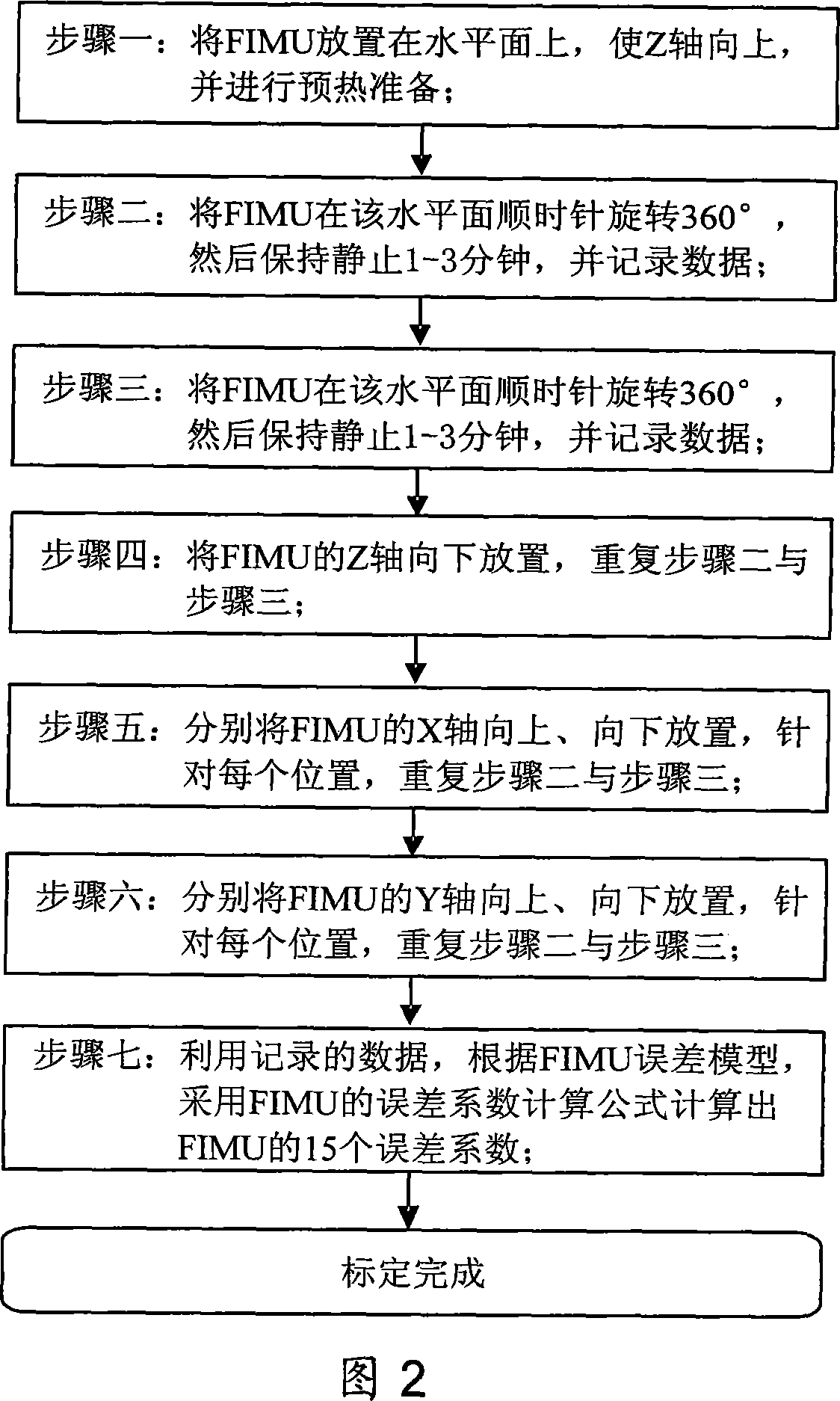
[0040] As shown in Figure 1 and Figure 2, the specific implementation steps of the present invention are as follows:

[0041] 1. Preparation of Fiber Optic Gyro Inertial Measurement Unit (FIMU)

[0042] Place the FIMU on a horizontal plane (the horizontal plane is not required to be absolutely horizontal, it can be tilted by ±5 degrees), so that the Z-axis of the FIMU is placed upwards, as shown in Figure 1a, start the FIMU, and wait for the FIMU to warm up.

[0043] 2. Rotate the FIMU counterclockwise 360° on the plane, then keep the FIMU stationary for 1-3 minutes, record the angular velocity and acceleration output by the FIMU during the rotation and stationary process, and establish the error model of the FIMU, such as formula (19) ~ formula ( 20) as shown:

[0044] SU=Aω+D (19)

[0045] kN=Cf+B (20)

[0046] Establish the error equation when the FIMU rotates counterclockwise around the Z axis, such as formula (21) ~ formula (24):

[0047] S z U z1 + =(ω z1 + +ω ...


PUM


Abstract

This is a live demarcating method for the fiber optic gyro inertial measurement Unit. This invention relates to a live demarcating method of the error coefficient of the fiber optic gyro inertial measurement Unit. This method can accurately demarcate 15 error coefficients such as the gyro calibration factor, normal value drift, erection error and the normal value bias through FIMU 12 whirl at six different positions without accurate rotating floor. This invention has such merits as high accuracy, simple operation which not only improves the working accuracy of FIMU but also improves the set efficiency.

Description

technical field [0001] The invention relates to a method for accurately calibrating the error coefficient of a fiber optic gyro inertial measurement unit (Fiber OpticGyro Inertial Measurement Unit, FIMU) on the spot, which can be used for calibrating the fiber optic gyro inertial measurement unit on the spot. Background technique [0002] The fiber optic gyroscope has the advantages of high precision, fast start-up, large dynamic range, anti-vibration shock and low cost, and is the development trend in the field of inertial instruments. In recent years, the rapid development of fiber optic gyro technology has promoted the application of fiber optic gyro strapdown inertial navigation systems in land, sea, air and space. The fiber optic gyro inertial measurement unit FIMU is the core component of the fiber optic gyro strapdown inertial navigation system. Its error includes two parts: deterministic error and random error. Among them, the deterministic error, that is, the system...

Claims


Application Information

Patent Timeline
IPC IPC(8): G01P21/00G01P15/14G01C25/00
Inventor 房建成刘百奇杨胜张海鹏宫晓琳韩晓英
Owner BEIHANG UNIV
Why Eureka
Try Eureka