Link junction method, port load equalizing method and apparatus thereof

A technology of link aggregation and port aggregation, applied in the field of data communication, to achieve the effect of reducing equipment costs

Inactive Publication Date: 2007-08-22
HUAWEI TECH CO LTD
View PDF0 Cites 43 Cited by
  • Summary
  • Abstract
  • Description
  • Claims
  • Application Information

AI Technical Summary

Problems solved by technology

In practice, almost no device has so many Ethernet ports, so it is

Method used


Image

  • Link junction method, port load equalizing method and apparatus thereof
  • Link junction method, port load equalizing method and apparatus thereof
  • Link junction method, port load equalizing method and apparatus thereof

Examples


Embodiment approach

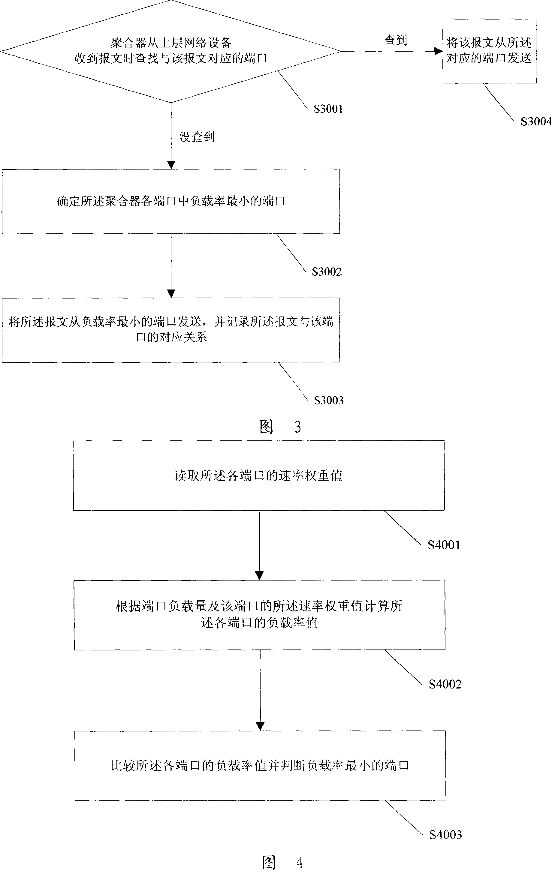
[0060] As an implementation manner, the load rate value of the port can be obtained by dividing the load amount of the port by the rate weight value of the port.

[0061] Step S4003: Compare the load rate values ​​of the ports and determine the port with the smallest load rate.

[0062] As an implementation manner, the port load may be understood as the number of packet flows loaded on the port. Of course, in practical applications, the actual traffic of each packet flow in some systems is not equal, and some packet flows may have a large flow, while some packet flows may have a small flow. In this case, the port The load can also be understood as the sum of the traffic of the packet flow loaded on the port.

[0063] Here, the rate weight value is a weight value corresponding to the rate assigned to each member port with a different rate when the aggregator is formed. As an implementation, the rate weight value of the port can be set to be proportional to the actual rate of ...


PUM


Abstract

A collecting method of links includes selecting port to be collected according to configuration information of local end port and opposite end port without considering speed rate information on order to let ports with different speed rates be able to be collected to be a collector and simultaneously setting port to be on speed weight valve corresponding to its speed rate in link collection process for making collector know relative speed rate of each port so as to carry out load-balancing of port. The port load-balancing method and its device are also disclosed.

Description

technical field [0001] The invention relates to the field of data communication, in particular to a link aggregation method, a port load balancing method and a device thereof. Background technique [0002] Link aggregation is a technology that aggregates multiple Ethernet links into one logical interface to improve bandwidth and reliability. The technical principle is: bind multiple Ethernet interfaces with the same attribute on a system to a logical interface, this logical interface is called an aggregator, and its subordinate Ethernet interfaces are called member ports. The aggregator provides packet processing services at the Ethernet link layer to upper-layer network devices and shields specific physical ports. When sending a message, the upper-layer network device only needs to send the message to the aggregator, and the aggregator distributes the message to one of its subordinate member ports according to certain principles, and the member port sends the message. Aft...

Claims


Application Information

Patent Timeline
IPC IPC(8): H04L29/06H04L12/56H04L45/741
Inventor 孙默
Owner HUAWEI TECH CO LTD
Why Eureka
Try Eureka