Partial load enabled falling film evaporator and method for operating a partial load

A technology of falling film evaporator and steam, which is applied in the direction of chemical instruments and methods, separation methods, vertical tube evaporators, etc.

Inactive Publication Date: 2007-08-22
ТІССЕНКРУПП УДЕ ҐМБГ
View PDF2 Cites 0 Cited by
  • Summary
  • Abstract
  • Description
  • Claims
  • Application Information

AI Technical Summary

Problems solved by technology

[0018] The second disadvantage is that the gases in the gas-vapor mixture can only be removed from the falling-film evaporator under difficult conditions if there is no longer enough residual pressure
[0019] Another problem is that if the gas in the gas-vapor mixture has an explosion zone

Method used


Image

  • Partial load enabled falling film evaporator and method for operating a partial load
  • Partial load enabled falling film evaporator and method for operating a partial load

Examples


Embodiment Construction

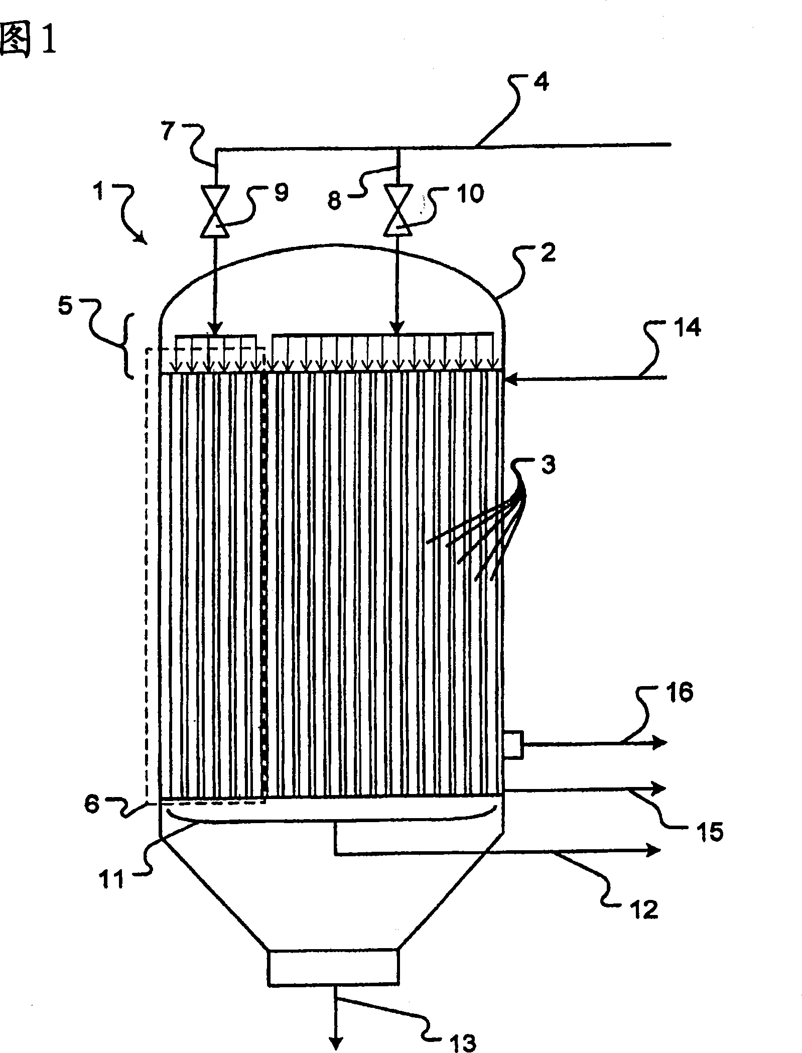
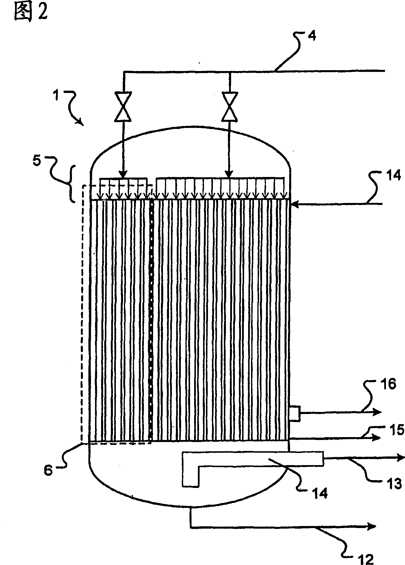
[0035] FIG. 1 shows a falling-film evaporator 1 with a surrounding casing 2 and a plurality of tubes 3 which are fastened at both ends in tube bases which are not shown in detail. The liquid in the feed line 3 is fed via the line 4 to the upper distribution device 5 and distributed via it to the two pipe sections, the smaller pipe section 6 being indicated by the dashed box. Line 4 is divided into two lines 7 and 8 according to the number of sections of distribution device 5 , wherein a valve 9 or 10 is provided in each of lines 7 and 8 so that the sections of distribution device 5 can be separated hydrodynamically from one another.

[0036] A collecting device 11 is arranged below the tube 3 , which receives the residual liquid from the tube 3 and leads it out of the falling film evaporator 1 through a line 12 . The vapors and gases flowing through the tubes 3 or formed there are discharged from the falling-film evaporator 1 via a line 13 .

[0037] The gas-vapor mixture is ...


PUM


Abstract

The invention relates to a falling film evaporator (1), which is fitted with a liquid distributor (5) which is divided into segments, such that it is possible to charge only a limited number of evaporator tubes (3) with liquid and the evaporator (1) can be operated in an optimum manner even with a partial load. The invention also relates to a method for operating said falling film evaporator (1), the aim of which is to transfer heat, which is released when a gas-vapour mixture is condensed, to a liquid which is to be evaporated at least partially. It would be useful to use said falling film evaporator (1) thus fitted in heat recuperation systems such as those used in the production of 1,2-dichloroethane.

Description

technical field [0001] Content of the present invention is a kind of falling film evaporator, it has at least: [0002] · A surrounding enclosure, [0003] a large number of tubes, on the inside of which a thin film of liquid can run down, [0004] means on the top surface for distributing the liquid into the individual tubes, [0005] · devices on the bottom to collect residual liquid and vapors, [0006] · a steam extraction device for the steam generated inside the tube, [0007] · a liquid extraction device for the non-evaporated liquid inside the tube, [0008] partitions, which separate the space inside the pipe and the devices hydraulically connected to it for distributing and collecting liquid from the space outside the pipe, [0009] a device for introducing a gas-vapor mixture into the space outside the tube, [0010] a device for draining condensate from the space outside the tube, [0011] • A device for removing non-condensable vapors and non-condensable ga...

Claims


Application Information

Patent Timeline
Patent Type & Authority Applications(China)
IPC IPC(8): B01D1/06
CPCY10S203/11Y10S203/07B01D1/065Y02P70/10B01D1/06
Inventor P·波尔沙M·本耶H·哈芬舍尔
Owner ТІССЕНКРУПП УДЕ ҐМБГ
Why Eureka
Try Eureka