Fuel injector with punch-formed valve seat for reducing armature stroke drift

A fuel injector and valve seat technology, applied in fuel injection pumps, fuel injection devices, charging systems, etc., can solve the problems of high engine emissions, high combustion noise, etc., and achieve the effect of avoiding plastic wear

Inactive Publication Date: 2007-09-19
ROBERT BOSCH GMBH
View PDF0 Cites 8 Cited by
  • Summary
  • Abstract
  • Description
  • Claims
  • Application Information

AI Technical Summary

Problems solved by technology

A higher fuel injection quantity into the combustion chamber of an internal combustion engine results in higher engine emissions and higher combustion noise

Method used


Image

  • Fuel injector with punch-formed valve seat for reducing armature stroke drift
  • Fuel injector with punch-formed valve seat for reducing armature stroke drift
  • Fuel injector with punch-formed valve seat for reducing armature stroke drift

Examples


Embodiment Construction

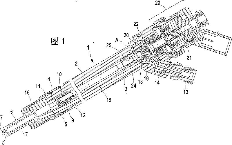
[0019] FIG. 1 shows a fuel injector for a high-pressure accumulator injection system.

[0020] A fuel injector 1 comprises an injector body 2 in which a valve piston 3 is guided. The valve piston 3 acts with an end face 4 on a pressure pin 5 formed on the nozzle needle 6 . At least one injection opening 7 is formed in the injector body 2 on the side facing the combustion chamber, not shown here. When the injection opening 7 is closed, the valve piston 3 exerts a pressure with its end face 4 on the pressure pin 5 of the nozzle needle 6 . The nozzle needle 6 is thus placed on a seat 8 and thus closes at least the injection opening 7 . In addition to the pressure of the valve piston 3 on the pressure pin 5 , a spring element 9 in the form of a compression spring acts on the nozzle needle 6 . The spring element 9 configured as a compression spring is preferably a helical spring. In the embodiment shown in FIG. 1 , this helical spring surrounds the pressure pin 5 of the nozzle ...


PUM


Abstract

The invention relates to a method for producing a fuel injector (1) for an internal combustion engine, having a control valve that releases from a control chamber (18) or closes an outlet throttle (20), whereby a closing element (22) is placed in a valve seat (26) for closing the outlet throttle (20). The closing seat (26) is produced by stamp-molding using a stamp (30). The invention also relates to a fuel injector which is produced by the inventive method.

Description

technical field [0001] In internal combustion engines with fuel injection systems, fuel is fed into the individual combustion chambers via fuel injectors with hydraulically actuated nozzle needles. For this purpose, a valve is accommodated in the fuel injector, which valve is controlled, for example, electromagnetically or by means of a piezoelectric actuator. Via this valve, the meter-out of a control chamber connected to the nozzle needle is released or closed. Background technique [0002] In the case of fuel injectors as known from the prior art, a valve element is accommodated in the housing of the fuel injector, in which valve element an outlet throttle is formed, which is connected to a control chamber. . The meter-out device is released or closed by a closing element. For this purpose, a conical valve seat is formed in the valve part, into which the meter-out throttle opens. To close the meter-out, a spherical closing element is seated in the conical valve seat. ...

Claims


Application Information

Patent Timeline
Patent Type & Authority Applications(China)
IPC IPC(8): F02M59/46F02M47/02F02M61/16
CPCF02M47/027F02M61/168F02M63/0036F02M63/0077
Inventor 马库斯·吕克勒阿克塞尔·施瑙费尔约阿希姆·莱希特
Owner ROBERT BOSCH GMBH
Why Eureka
Try Eureka