Fuel injector with punch-formed valve seat for reducing armature stroke drift

一种燃料喷射器、阀座的技术,应用在燃料喷射泵、燃料喷射装置、装料系统等方向,能够解决高发动机排放、高燃烧噪音等问题,达到避免塑性地磨损的效果

Inactive Publication Date: 2010-06-16
ROBERT BOSCH GMBH
View PDF4 Cites 0 Cited by
  • Summary
  • Abstract
  • Description
  • Claims
  • Application Information

AI Technical Summary

Problems solved by technology

A higher fuel injection quantity into the combustion chamber of an internal combustion engine results in higher engine emissions and higher combustion noise

Method used


Image

  • Fuel injector with punch-formed valve seat for reducing armature stroke drift
  • Fuel injector with punch-formed valve seat for reducing armature stroke drift
  • Fuel injector with punch-formed valve seat for reducing armature stroke drift

Examples


Embodiment Construction

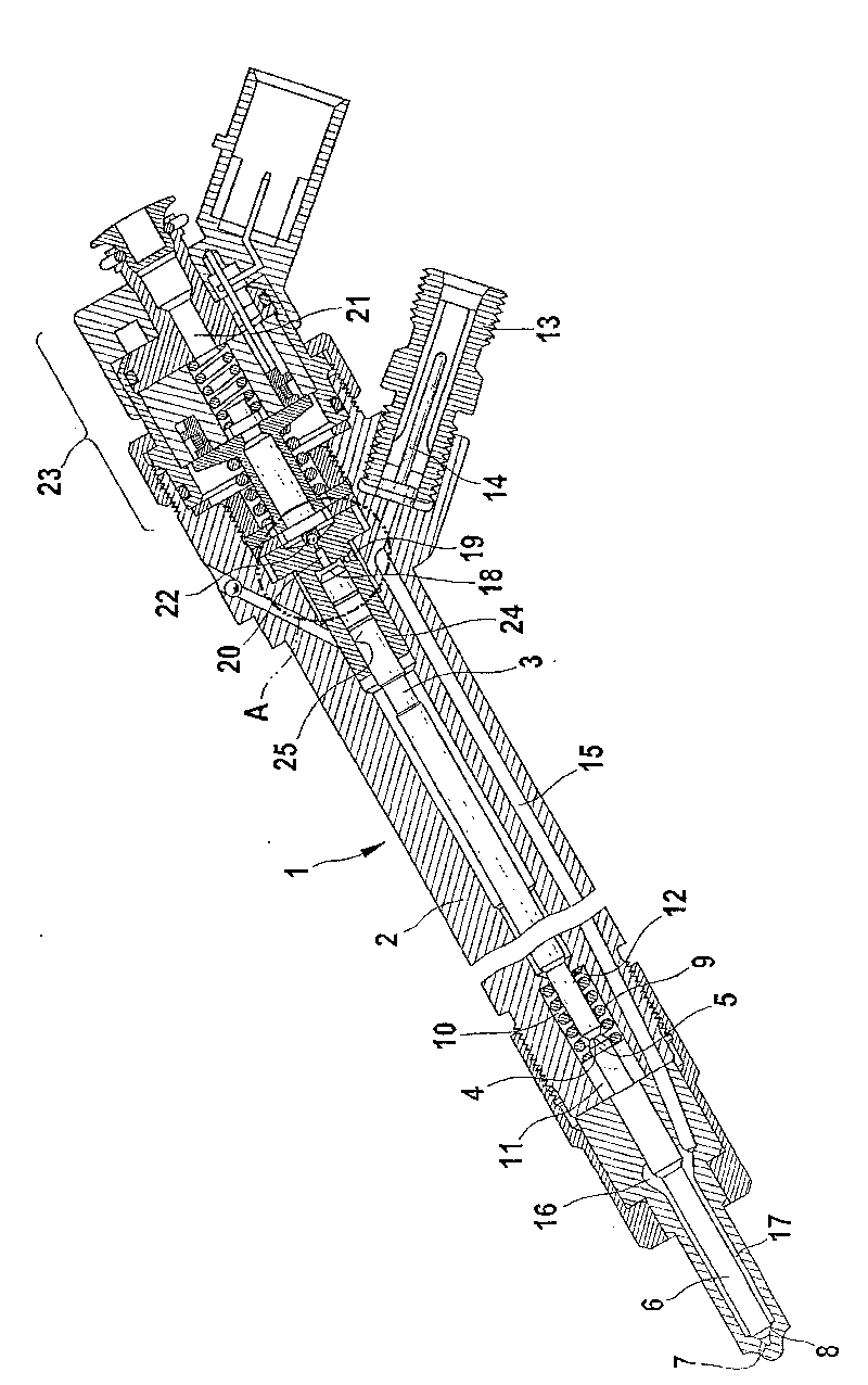
[0019] figure 1 A fuel injector for a high-pressure accumulator injection system is shown.

[0020] A fuel injector 1 comprises an injector body 2 in which a valve piston 3 is guided. The valve piston 3 acts with an end face 4 on a pressure pin 5 formed on the nozzle needle 6 . At least one injection opening 7 is formed in the injector body 2 on the side facing the combustion chamber, not shown here. When the injection opening 7 is closed, the valve piston 3 exerts a pressure with its end face 4 on the pressure pin 5 of the nozzle needle 6 . The nozzle needle 6 is thus placed on a seat 8 and thus closes at least the injection opening 7 . In addition to the pressure of the valve piston 3 on the pressure pin 5 , a spring element 9 in the form of a compression spring acts on the nozzle needle 6 . The spring element 9 configured as a compression spring is preferably a helical spring. exist figure 1 In the embodiment shown, this helical spring surrounds the pressure pin 5 of ...


PUM


Abstract

The invention relates to a method for producing a fuel injector (1) for an internal combustion engine, having a control valve that releases from a control chamber (18) or closes an outlet throttle (20), whereby a closing element (22) is placed in a valve seat (26) for closing the outlet throttle (20). The closing seat (26) is produced by stamp-molding using a stamp (30). The invention also relatesto a fuel injector which is produced by the inventive method.

Description

technical field [0001] In internal combustion engines with fuel injection systems, fuel is fed into the individual combustion chambers via fuel injectors with hydraulically actuated nozzle needles. For this purpose, a valve is accommodated in the fuel injector, which valve is controlled, for example, electromagnetically or by means of a piezoelectric actuator. Via this valve, the meter-out of a control chamber connected to the nozzle needle is released or closed. Background technique [0002] In the case of fuel injectors as known from the prior art, a valve element is accommodated in the housing of the fuel injector, in which valve element an outlet throttle is formed, which is connected to a control chamber. . The meter-out device is released or closed by a closing element. For this purpose, a conical valve seat is formed in the valve part, into which the meter-out throttle opens. To close the meter-out, a spherical closing element is seated in the conical valve seat. ...

Claims


Application Information

Patent Timeline
Patent Type & Authority Patents(China)
IPC IPC(8): F02M59/46F02M47/02F02M61/16
CPCF02M47/027F02M63/0077F02M61/168F02M63/0036
Inventor 马库斯·吕克勒阿克塞尔·施瑙费尔约阿希姆·莱希特
Owner ROBERT BOSCH GMBH
Why Eureka
Try Eureka