Optical element, display device, and terminal device

A display device and optical element technology, applied in optics, identification devices, nonlinear optics, etc., can solve problems such as inability to fully reduce moiré fringes, and achieve the effects of preventing peeping, improving directivity, high transmittance and brightness

Active Publication Date: 2007-09-26
NEC LCD TECH CORP
View PDF4 Cites 21 Cited by
  • Summary
  • Abstract
  • Description
  • Claims
  • Application Information

AI Technical Summary

Problems solved by technology

For these reasons, it is practically impossible to perform tilted configurations at large angles to sufficiently reduce moiré
Moreover, as shown in FIG. 6, when the pitch of the light-shielding layer of the light direction limiting element is close to the pixel pitch of the display device, since the period of the moiré fringe increases, even if it is arranged obliquely, the moiré cannot be sufficiently reduced. stripe

Method used


Image

  • Optical element, display device, and terminal device
  • Optical element, display device, and terminal device
  • Optical element, display device, and terminal device

Examples


Embodiment Construction

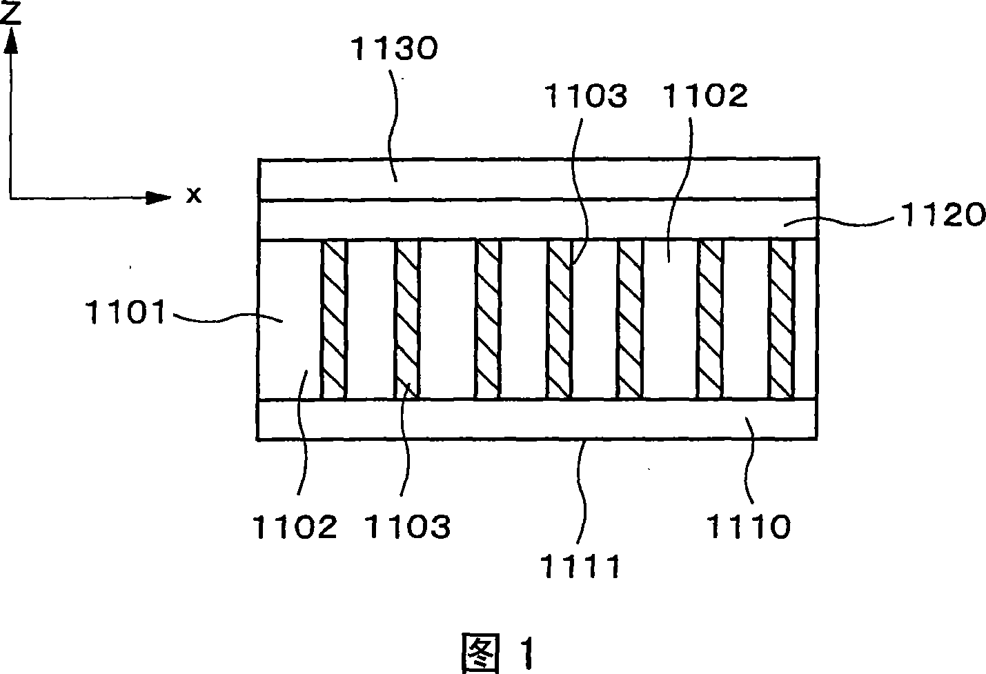
[0082] An optical element, a display device, and a terminal device according to embodiments of the present invention will be specifically described with reference to the drawings. First, the optical element according to the first embodiment of the present invention will be described in detail based on the principle of operation.

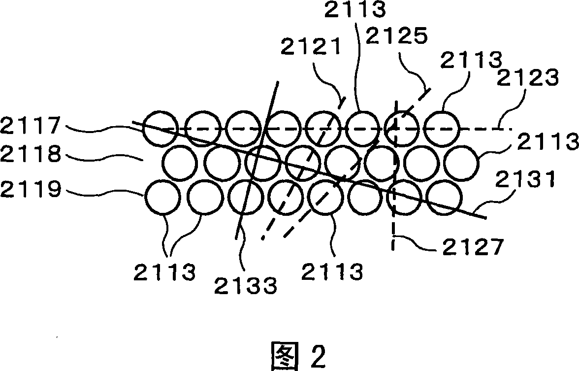
[0083] The optical element according to the first embodiment of the present invention is a light direction limiting element in which transparent regions and opaque regions are alternately and periodically arranged one-dimensionally on a plane, and a two-dimensional grid in which transparent regions and opaque regions are alternately and periodically arranged two-dimensionally Sheets are stacked together. The light direction limiting element has one-dimensional translational symmetry based on the one-dimensional periodic structure, and the two-dimensional grid sheet has two-dimensional translational symmetry based on the two-dimensional grid structure...


PUM

PropertyMeasurementUnit
thicknessaaaaaaaaaa
sizeaaaaaaaaaa

Abstract

A plurality of pixels is arranged periodically in the x-axis direction and the y-axis direction in the display panel of a display device, and because light is blocked by the portion other than the open part in each pixel, the display panel has a two-dimensional lattice structure. The pixels are rectangular, and the length Px of the long edges in the x direction is larger than the length Py of the short edges in the y direction. A louver, in which transparent regions and non-transparent regions are arranged periodically in a one-dimensional direction, is provided on the display panel, and the angle formed by the x axis and the one-dimensional period direction of the louver is 45 degrees or less, and preferably 10 degrees or less. This configuration makes it possible to obtain an optical element having high directivity, reduced moire, and high transmittance. It is also possible to obtain a display device having excellent display quality into which the optical element is incorporated.

Description

technical field [0001] The present invention relates to a display device that reduces moire to achieve superior display quality. Background technique [0002] With the development of recent technologies, display panels are widely used in a variety of devices, including monitors, televisions and other large terminal devices; notebook PCs (personal computers), ATMs, vending machines and other medium-sized terminal devices ; and personal TV (television), PDA (personal digital assistant: personal information terminal), mobile phone, mobile game console and other small terminal devices. Liquid crystal display devices using liquid crystals are particularly popular in terminal devices due to their advantages of thinness, light weight, small size, and low power consumption. [0003] Among these terminal devices, small and medium-sized terminal devices are characteristically used not only in highly secure secret rooms but also in public places. At this time, it is necessary to prev...

Claims


Application Information

Patent Timeline
Patent Type & Authority Applications(China)
IPC IPC(8): G02F1/1335G02F1/1333G09F9/00H04M1/02
CPCG02F1/134363G02F2201/124G02F1/133509
Inventor 新冈真也上原伸一住吉研金子节夫
Owner NEC LCD TECH CORP
Why Eureka
Try Eureka