Retarder

A gear reducer, gear technology, applied in the direction of gear transmission, belt/chain/gear, mechanical equipment, etc., can solve the problems of poor accuracy, difficult to achieve high reduction ratio, etc., to achieve low cost, high reduction ratio. Effect

Active Publication Date: 2007-10-03
SUMITOMO HEAVY IND LTD
View PDF2 Cites 5 Cited by
  • Summary
  • Abstract
  • Description
  • Claims
  • Application Information

AI Technical Summary

Problems solved by technology

However, since the three eccentric shafts 30 are not rotated at the same time, there is deviation of the backlash, which is not good in accuracy.
In addition, only the reduction ratio at the meshing (or connecting) portion of the pinion (or pulley) 14 and the input gear (or input pulley) 20 works, and it is difficult to achieve a high reduction ratio

Method used


Image

  • Retarder
  • Retarder
  • Retarder

Examples


Embodiment Construction

[0024] Hereinafter, an example of embodiment of the present invention will be described in detail using the drawings.

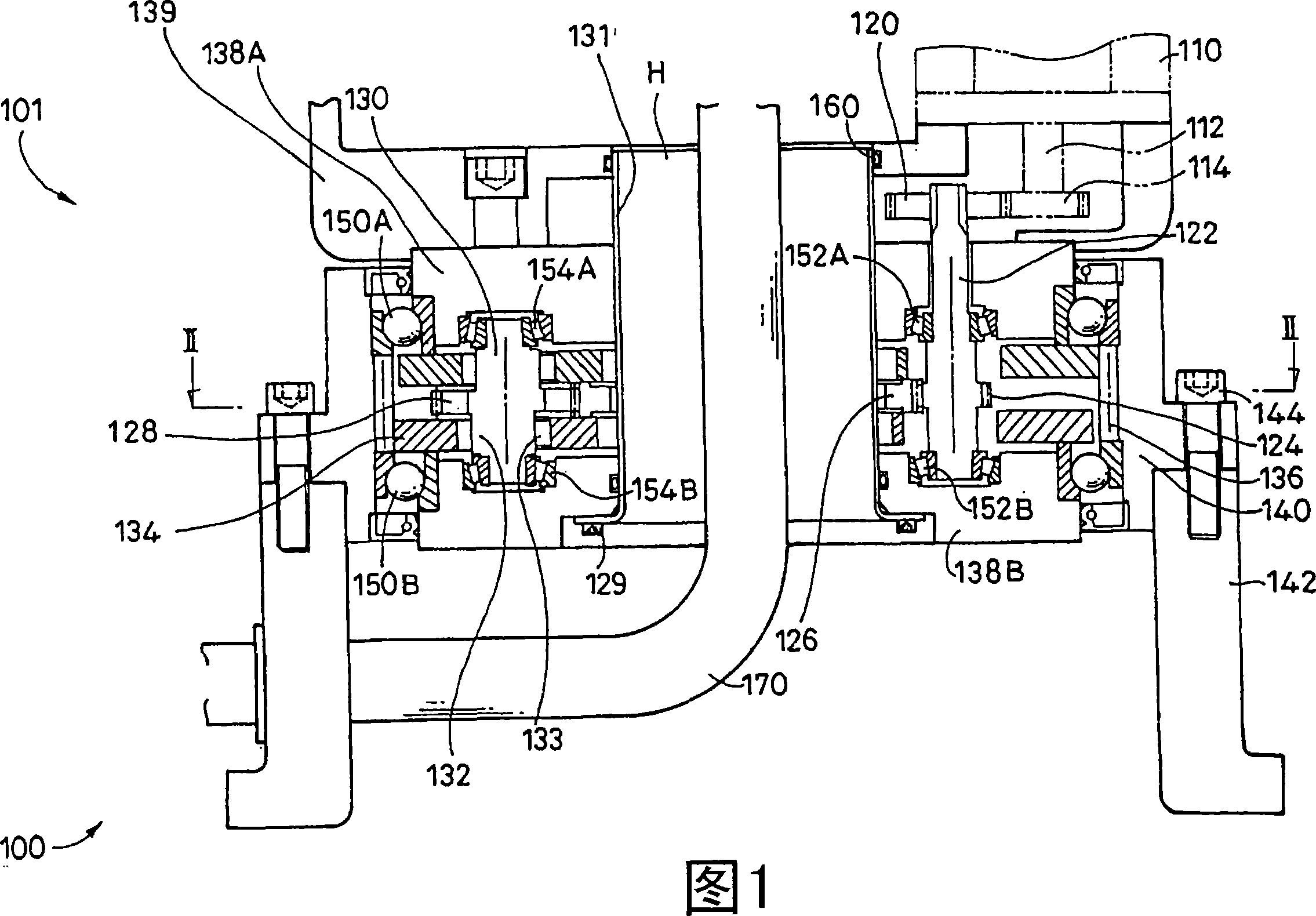
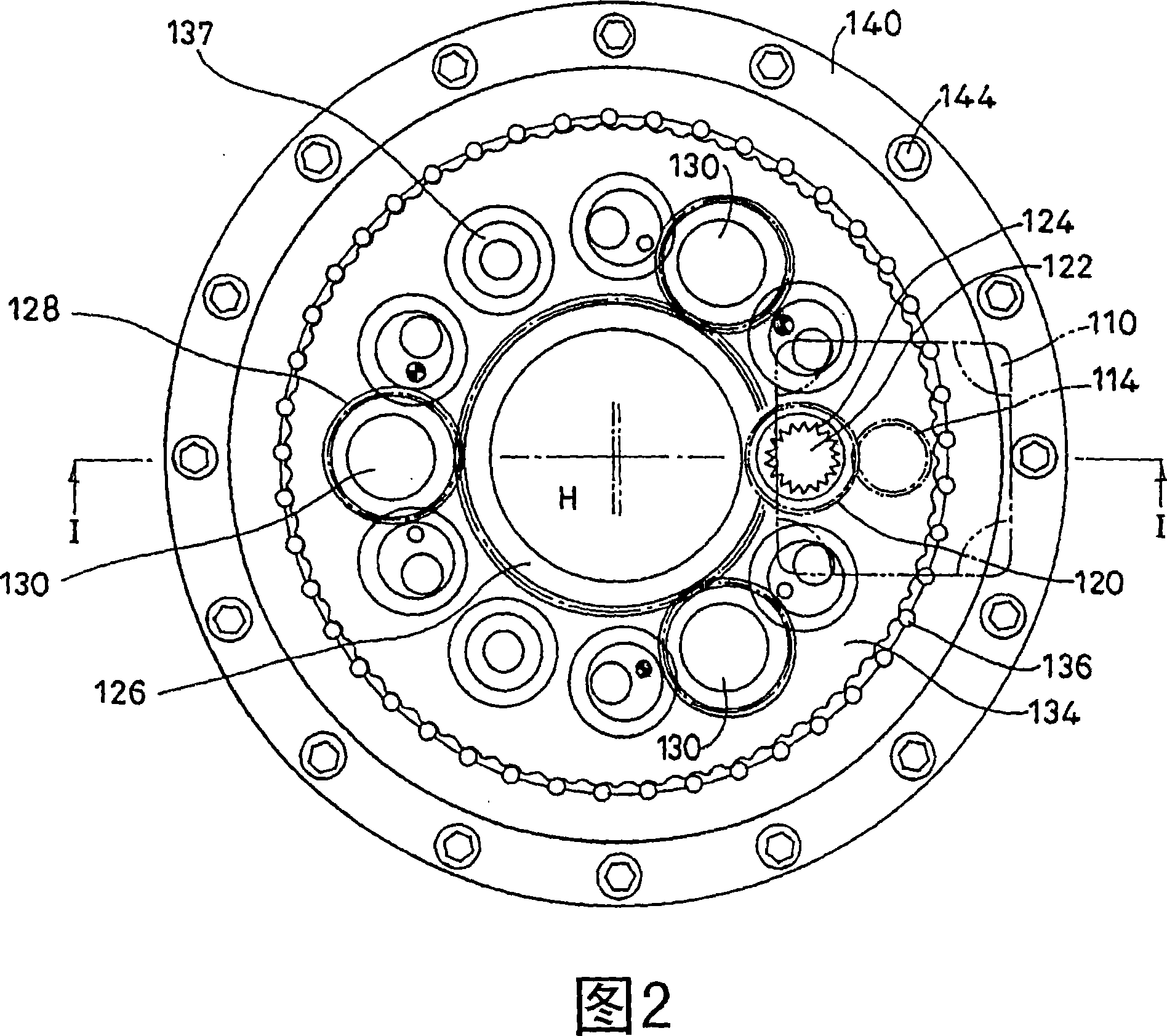
[0025] FIG. 1 is a side sectional view showing a gear motor 100 according to an embodiment of the present invention, and FIG. 2 is a sectional view taken along arrow II-II in FIG. 1 .

[0026] The gear motor 100 is composed of a motor 110 as a power source and an inscribed swing engagement type planetary gear reducer 101 . The gear motor 100 is a so-called "vertical" gear motor 100 in which its axial direction is the up-down direction. The motor 110 is provided on the upper surface side of a housing 140 for accommodating the speed reduction mechanism, and a base 142 is connected to the lower surface side of the housing 140 by screws 144 . In addition, a hollow portion H is provided in the center portion in the radial direction of the gear motor 100 , and the cable 170 or the like can be passed through the hollow portion H for use.

[0027] The air portion H...


PUM


Abstract

To provide an oscillating internally meshing planetary gear reducer capable of realizing a low cost and a high speed reduction ratio, the oscillating internally meshing type planetary gear reducer is constituted so as to include: an input shaft provided with an input gear which is circumscribed and meshed with a pinion provided on a motor; an input shaft gear formed on the input shaft; a plurality of eccentric body shafts each provided with an eccentric body for oscillating an oscillating external gear; an eccentric body shaft gear which is formed on each eccentric body shaft; and a distributing gear which is meshed with the input shaft gear and the eccentric body shaft gear.

Description

technical field [0001] The invention relates to an inscribed oscillating engagement type planetary gear reducer. Background technique [0002] Conventionally, the gear motors 1, 2 and 2' described in (Japanese) Unexamined Patent Publication No. 2002-106650 or (Japanese) Unexamined Patent Application Publication No. 2002-122190 are known. [0003] FIG. 6 shows the geared motor 1 described in JP-A-2002-106650. FIG. 7 shows the geared motor 2 described in JP-A-2002-122190. FIG. 8 shows a gear motor 2' described in JP-A-2002-122190. In addition, the same or similar parts of these respective gear motors are described with the same reference numerals. [0004] Each gear motor includes a motor 10 as a power source, a pinion or pulley 14 equipped on a motor shaft 12 of the motor 10, an eccentric body shaft 30 provided with an eccentric body 32 for swinging an externally toothed gear 34, and an unloading external gear motor. The carrier 38 (38A, 38B) of the rotation component of ...

Claims


Application Information

Patent Timeline
IPC IPC(8): F16H1/28
Inventor 芳贺卓为永淳
Owner SUMITOMO HEAVY IND LTD
Why Eureka
Try Eureka