

Grid drive circuit, liquid crystal display device and electronic device
A technology of gate drive circuit and liquid crystal display device, which is applied to static indicators, instruments, etc., and can solve problems such as image color shift and current drive capability reduction
- Summary
- Abstract
- Description
- Claims
- Application Information
AI Technical Summary
Problems solved by technology
Method used
Image

Examples
Embodiment Construction
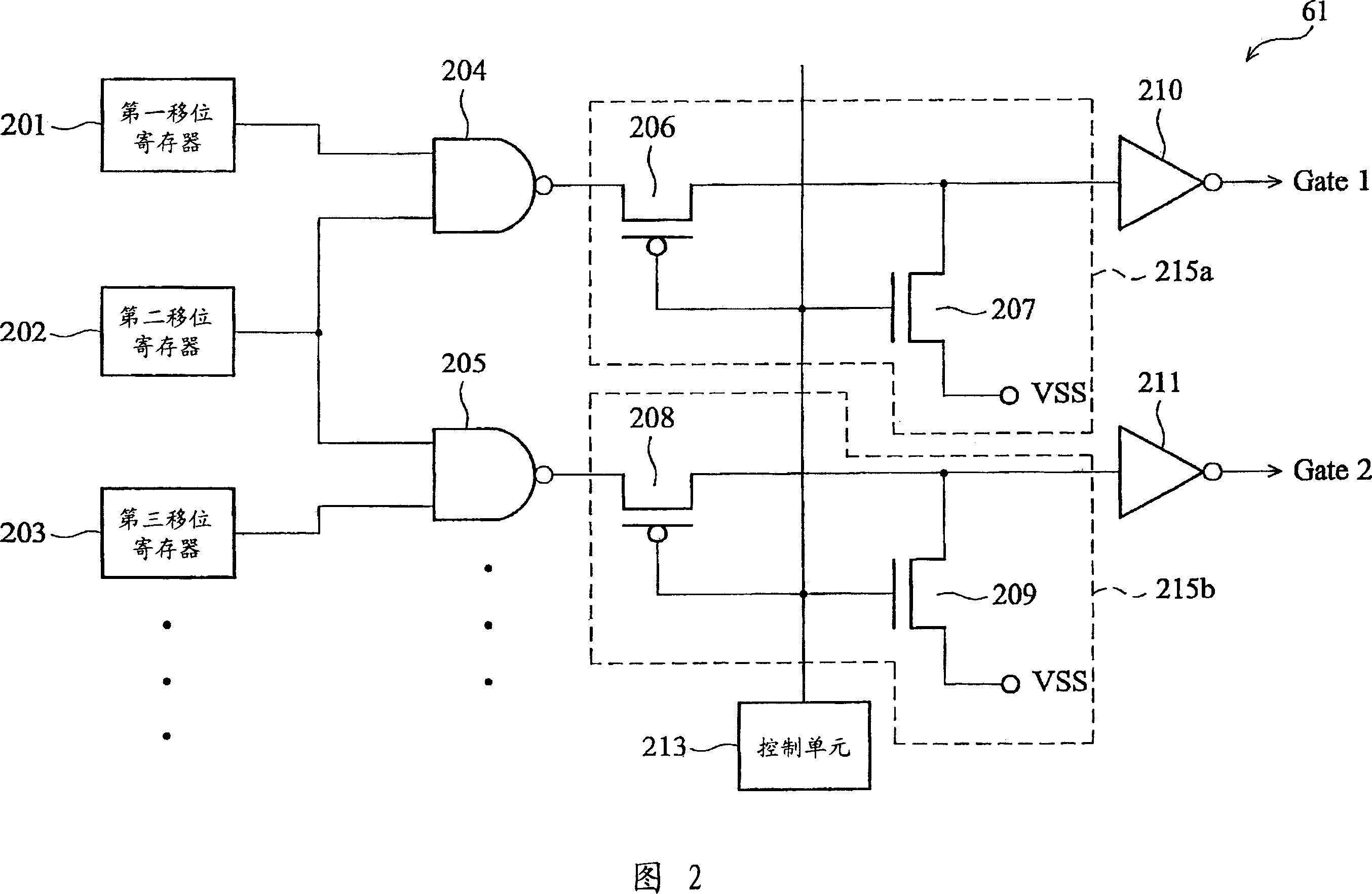
[0031] FIG. 2 is a schematic diagram of an embodiment of a gate driving circuit according to the present invention. A plurality of shift registers are included in the gate driving circuit 61 , and only three shift registers are used for illustration in this embodiment, which is not intended to limit the present invention. The control unit 213 is used to output a control signal Dreset. In this embodiment, when the liquid crystal panel is turned on, the control signal Dreset is logic low level, and when the liquid crystal panel is turned off, the control signal Dreset is logic high level. The NAND gate 204 has two input terminals respectively coupled to the first shift register 201 and the second shift register 202 . The NAND gate 204 is coupled to the input terminal of the inverter 210 through the selection unit 215a. The selection unit 215a is controlled by a control signal Dreset, so that the inverter 210 receives a voltage signal of a logic low level. The selection unit 21...
PUM
 Abstract
Description
Claims
Application Information