Press-slide switch

A sliding switch and button technology, applied in electrical switches, electrical components, circuits, etc., can solve problems such as increased damage or misoperation, entry of foreign objects, and clamping of foreign objects, etc., to achieve a keen sense of operation, reliable operation, and shorten the pressing stroke. Effect

Inactive Publication Date: 2007-10-03
MITSUMI ELECTRIC CO LTD
View PDF1 Cites 3 Cited by
  • Summary
  • Abstract
  • Description
  • Claims
  • Application Information

AI Technical Summary

Problems solved by technology

[0005] When not in operation, the button part of the operation switch protrudes from the machine operation panel surface, and the button part is easy to touch the article, and the damage or misoperation also increases.
In addition, during operation, the amount of intrusion into th

Method used


Image

  • Press-slide switch
  • Press-slide switch
  • Press-slide switch

Examples


Embodiment

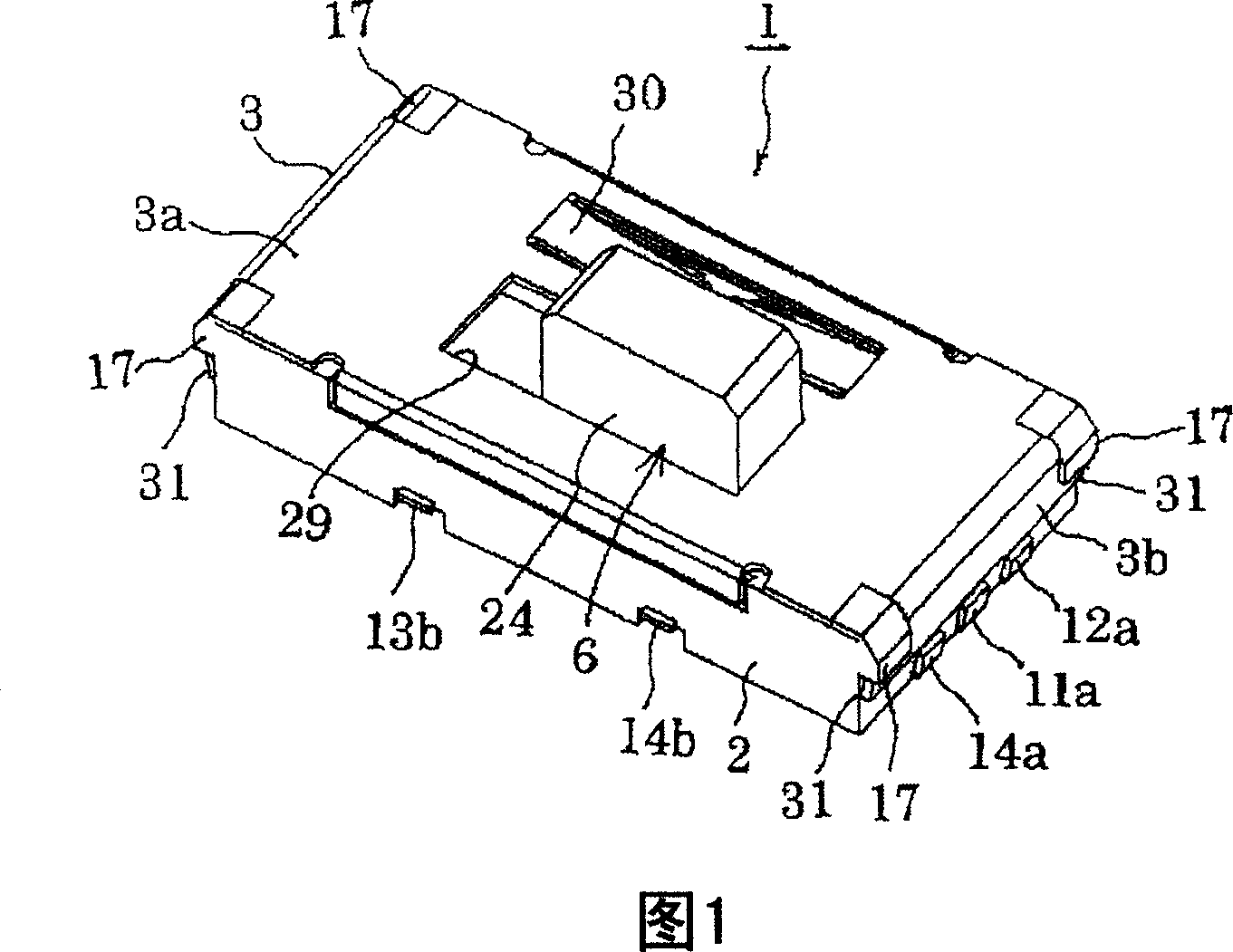
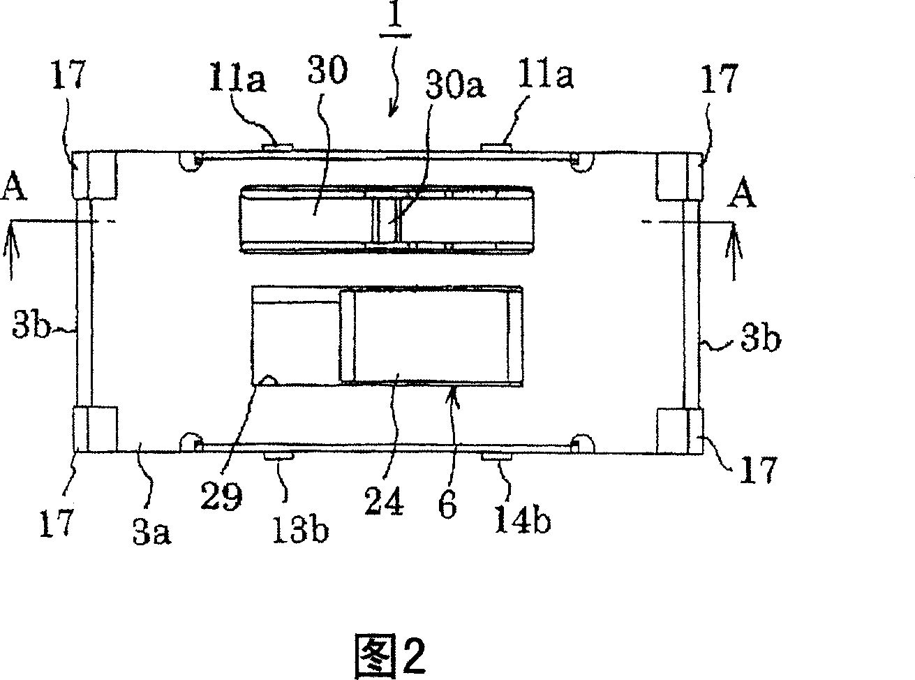
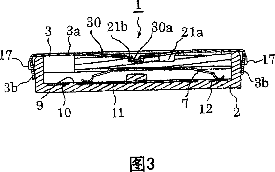
[0032] 1 to 7 show an embodiment of the present invention. As shown in FIG. 4, the push / slide switch 1 is composed of a base 2, a cover 3, an operating member 6 composed of a first operating member 4 and a second operating member 5, a sliding contact piece 7, and a disc-shaped movable contact piece 8. .

[0033] The base 2 is formed into a thin and roughly box-shaped by an insulating member such as a synthetic resin material. As shown in FIG. Arranged in a row, the fixed terminals for pressing 13 and 14 are fixed in parallel with the fixed terminals for sliding 10 to 12 by insert molding. The terminal portions 10a-12a, 11b, 11b of the sliding fixed terminals 10-12 and the terminals 13a, 14a, 13b, 14b of the pressing fixed terminals 13, 14 are drawn out of the base 2 and exposed. In addition, the fixed terminals 13 and 14 for pressing are exposed in the concave portion 15 of the inner bottom surface 9 .

[0034] 6 shows the shape and arrangement state of the sliding fixed te...


PUM


Abstract

The present invention provides a push/slide switch capable of shortening the push stroke and achieving miniaturization and sharp operation feeling. It is composed of the following parts: a base that holds a plurality of fixed terminals for sliding and a plurality of fixed terminals for pressing; a cover that has an opening for a button and covers the base; and is movable in the left and right directions and is arranged to face the fixed terminals for sliding , the sliding piece that switches the connection between the fixed terminals for sliding through the movement in the left and right directions; it is arranged opposite to the fixed contact for pressing, and when the center is pressed, it elastically reverses and switches the connection between the fixed contacts for pressing. and a button part protruding outward through the button opening of the cover, and covers the sliding contact and the disc-shaped movable contact and is housed in the cover, and can slide in the left and right direction together with the sliding contact, and An operating member that can move in the up and down direction of the pressed disc-shaped movable link when pressed in the pressing direction.

Description

technical field [0001] The present invention relates to a push / slide switch, and more particularly, to a push / slide switch that can be used regardless of the push switch or the slide switch by the operation of one button. Background technique [0002] Conventionally, a push / slide switch is known that can be used regardless of whether it is a push switch or a slide switch by operating a single button (for example, refer to Patent Document 1-JP-A-2001-229781). [0003] In the push / slide switch known in Patent Document 1, both the slide switch function part and the push switch function part employ a sliding contact method. [0004] However, in the push / slide switch described in Patent Document 1, since both the slide switch function part and the push switch function part use the sliding contact method, there is a problem that the push stroke becomes large. The pressing stroke is large, and the following problems arise in the design of a device incorporating the push / slide swit...

Claims


Application Information

Patent Timeline
IPC IPC(8): H01H25/00H01H15/24H01H13/52
Inventor 河村乔寺下俊彦川口繁实中村哲也菊池秀武佐佐木隆裕
Owner MITSUMI ELECTRIC CO LTD
Why Eureka
Try Eureka