Method for protecting 1+1 single sub-network connection and communication network using the method

A communication network, one-way technology, applied in the field of communication network, to achieve the effect of enhancing reliability

Inactive Publication Date: 2007-10-03
刘真
View PDF0 Cites 15 Cited by
  • Summary
  • Abstract
  • Description
  • Claims
  • Application Information

AI Technical Summary

Problems solved by technology

This shortcoming is more prominent when A / B / B', C / C' / D belong to different operators

Method used


Image

  • Method for protecting 1+1 single sub-network connection and communication network using the method
  • Method for protecting 1+1 single sub-network connection and communication network using the method
  • Method for protecting 1+1 single sub-network connection and communication network using the method

Examples


Embodiment Construction

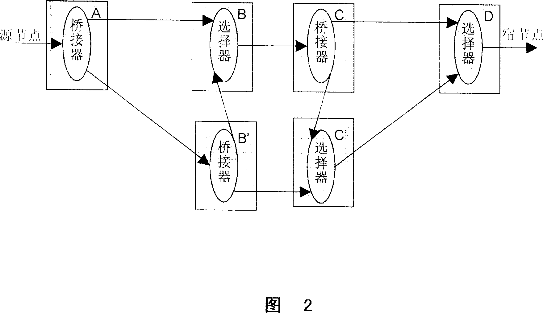
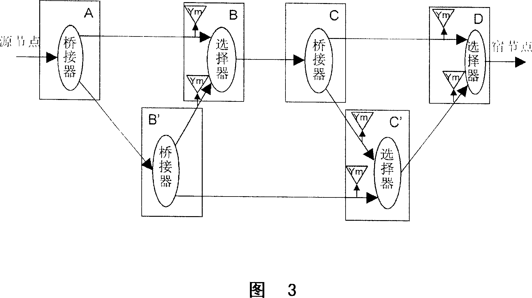
[0023] Figure 2 is a protection architecture according to a first embodiment of the present invention. As shown in Figure 2, the bridge at source node A duplicates the input signal into two copies and sends them to the two downstream nodes respectively. For example, node B' copies the signal from node A and sends it to B and C'. The selector completes the selection of signals. For example, node B needs to select one of the two signals from A and B' and send it downstream. How to select is related to the specific mode, which will be described in detail below.

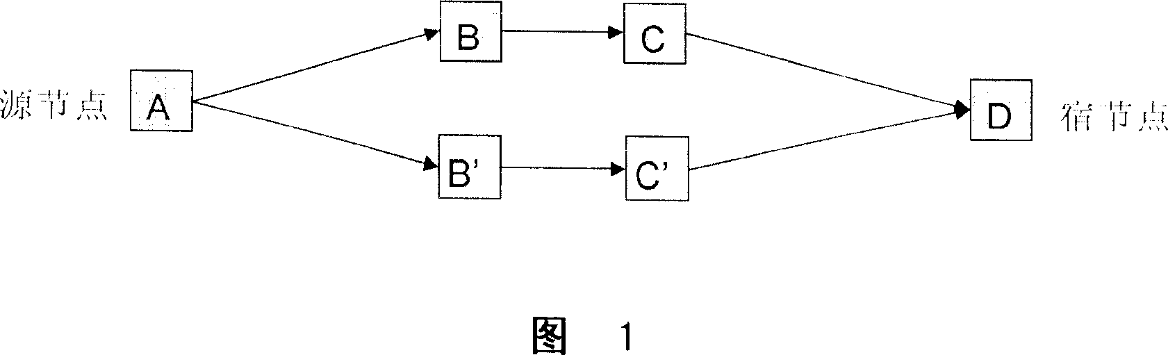
[0024] It should be noted that the connection between two nodes in the figure can be through an intermediate node, and whether there is an intermediate node does not affect the integrity of the architecture description and the feasibility of implementation. In addition, the source node and sink node in the figure are not the source and sink of services, but the source and sink of subnet connections. That is, the sour...


PUM


Abstract

A communication network used for realizing service protection of 1+1 end to end one-way sub-network connection consists of source node, host node, the first and the second paths between two said nodes, the first bridge at source node, the first selector at host node, the second selector and the second bridge at the first path and the third bridge as well as the third selector at the second path.

Description

technical field [0001] The invention relates to a communication network, in particular to a method for realizing 1+1 end-to-end unidirectional subnet connection service protection in the communication network, and a communication network using the method. Background technique [0002] Subnet Connection Protection (SNCP) is an important type of protection in a transport network, and can support cascaded protection subnets. Such a network architecture can recover services in case of multi-point failure (each protected subnet can have one failure point). Refer to Figure 19 in Chapter 11.2 of ITU-T G.808.1. [0003] FIG. 1 is an end-to-end 1+1E2E protection mode in the prior art. As shown in Figure 1, two E2E connections are established from source node A to sink node D. The source node sends signals from two connections, and the sink node selects a signal from a normal connection according to the status of the two connections. [0004] However, this protection method cannot...

Claims


Application Information

Patent Timeline
Patent Type & Authority Applications(China)
IPC IPC(8): H04L12/24H04L12/46
CPCH04L12/66H04L12/46H04L45/00H04L45/24H04L45/28
Inventor 何健飞
Owner 刘真
Why Eureka
Try Eureka