
Electronic clutch type driver for electronic lock

A driving device and clutch-type technology, applied in the field of locks, can solve the problems of loss of flexibility, short service life, pulling of inner and outer clutch sleeves, etc., and achieve the effects of fast opening speed, long service life and high torque bearing force.

Inactive Publication Date: 2007-10-10
夏志云
View PDF0 Cites 2 Cited by
  • Summary
  • Abstract
  • Description
  • Claims
  • Application Information

AI Technical Summary

Problems solved by technology

The defect is: the screw rod is easy to wear when the motor rotates at a high speed, and the elastic spring stuck in the middle will wear even more when the pin hole is deviated, resulting in sometimes the lock cannot be opened and the service life is short
Defect is: when unlocking, due to the use of motor transmission, the complete insertion of the latch can not be completed instantly in time, generally more than half a second, and pressing the handle when encountering impatience will cause the shaft pin and the plug of the clutch mechanism to deform and roll. Injury, internal and external clutch sleeve pulling, eccentricity, etc., so that it becomes a bad lock
[0005] 3. Locking and stuck fault: The plug-type clutch mechanism can only be fully inserted at the punctual point where the inner and outer shafts are synchronized, and the deflection angle is small
Over time, the general door will fall and the lock tongue will not be fully extended, and the oil on the factory will be dry. It is impossible for the user to adjust the height of the door and remove the lock on time. Over time, the rotating parts such as the handle and the lock tongue It will lose flexibility, in case the door is not reset when the door is closed and locked, it will not be possible to unlock and enter the house when you are outside

Method used


Image

  • Electronic clutch type driver for electronic lock
  • Electronic clutch type driver for electronic lock
  • Electronic clutch type driver for electronic lock

Examples


Embodiment 1

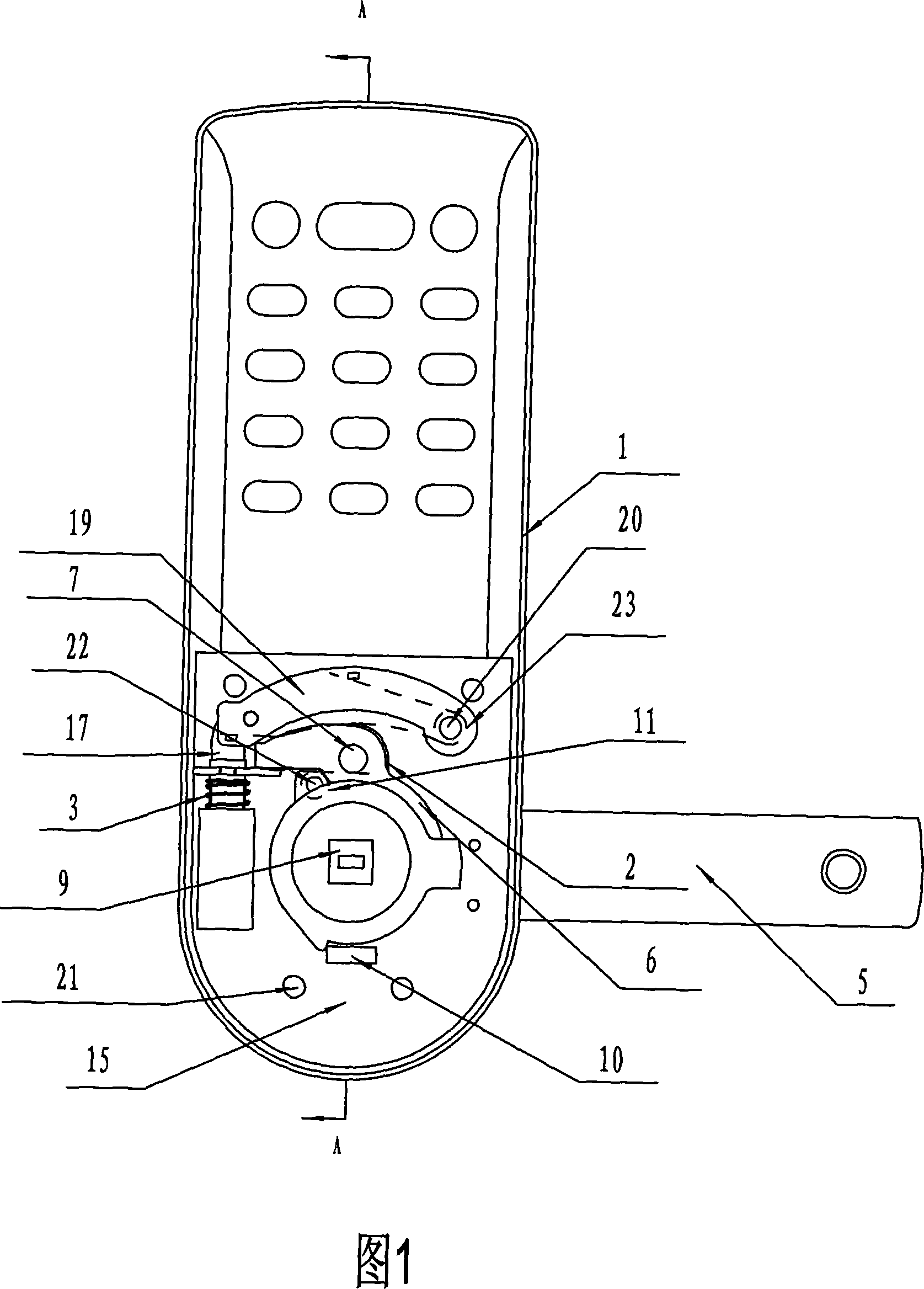
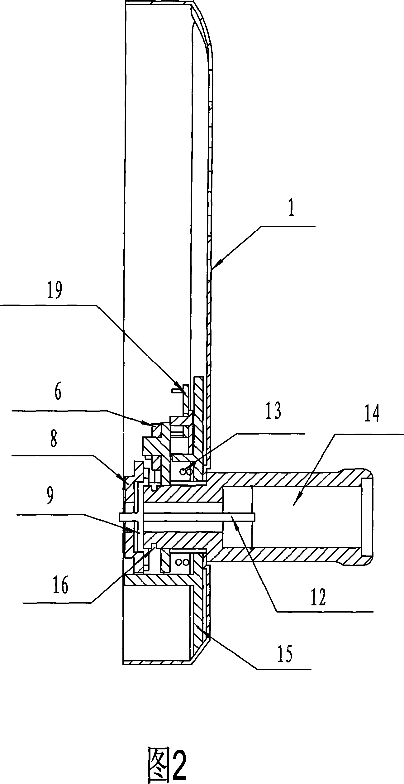
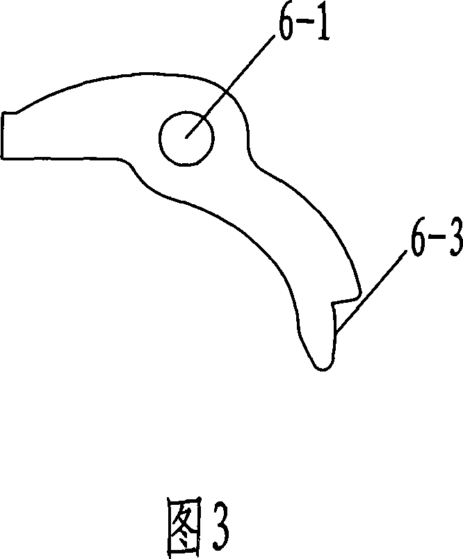
[0038] Embodiment 1: This electronic lock electronic clutch driving device mainly includes an outer panel 1 and a handle 5 , the outer panel 1 is provided with a fixing screw hole 21 , and the outer panel 1 is fixedly connected with a liner 15 . The 5 shafts of the handle are fixedly connected with a handle spline buckle 2, the handle spline buckle 2 is provided with a square bar spline keyboard 8, and the handle spline buckle 2 is connected with a clutch buckle 6 through a clutch pin shaft pin 7, and the clutch buckle One end of 6 is provided with clutch buckle card groove 6-3, is provided with square rod hole 8-1, flower keyboard card groove 8-2 and flower keyboard folding edge 8-3 on the square bar flower keyboard 8, wherein flower keyboard card groove 8 -2 cooperates with the positioning block 10 on the lining plate 15, and the flower keyboard flange 8-3 is clutched with the clutch buckle slot 6-3; the output shaft of the electromagnet 4 is provided with a connecting piece ...

Embodiment 2

[0045] Embodiment 2: The difference from Embodiment 1 is that there is no lock core structure, only an electromagnet structure. This structure is relatively simple. The lock core part is removed from the drawing of Embodiment 1. This electronic lock electronic clutch driving device mainly includes an outer panel 1 and a handle 5. The handle 5 is fixedly connected with a handle spline buckle 2. The key buckle 2 is connected with the clutch buckle 6 through the clutch buckle pivot pin 7, one end of the clutch buckle 6 is provided with the clutch buckle card slot 6-3, and the square stick flower keyboard 8 is provided with the square stick hole 8-1, the flower keyboard card Groove 8-2 and keypad flap 8-3, wherein keypad card slot 8-2 cooperates with positioning block 10 on the outer panel, keypad flap 8-3 and clutch buckle slot 6-3 are clutch type Cooperate; the output shaft of the electromagnet 4 is provided with a connecting piece 17 and an electromagnet spring 3, the connectin...


PUM


Abstract

The present invention relates to an electronic engagement and disengagement type drive device for electronic lock. Said drive device includes the following several main portions: external panel, handle, handle shaft, handle spline fastener, square bar spline disk, engagement and disengagement fastener, engagement and disengagement fastener retaining slot, electromagnetic iron and its output shaft, engagement and disengagement fastener control block and connecting piece, etc. Besides, also provides the connection mode of all the above-mentioned portions, and also provides the working principle of said drive device and its operation method.

Description

technical field [0001] The invention relates to the field of locks, and mainly relates to an electronic clutch driving device for an electronic lock. Background technique [0002] The current high-end electronic lock clutch mechanism is easy to jam mainly for the following reasons: [0003] 1. Motor transmission structure: The unlocking control mechanism is mainly completed by the motor plus the screw rod to drive the elastic spring back and forth. Defect is: the high screw rod of motor rotating speed is easy to wear and tear, and elastic spring is clamped in the middle section and can wear more when meeting bolt hole deviation, causes sometimes also can't open lock and short service life. [0004] 2. Mechanical clutch mechanism: most of the clutch mechanism is completed by push-pull shaft pin and insert block. Defect is: when unlocking, due to the use of motor transmission, the complete insertion of the latch can not be completed instantly in time, generally more than hal...

Claims


Application Information

Patent Timeline
Patent Type & Authority Applications(China)
IPC IPC(8): E05B47/02E05B49/00
Inventor 夏士林
Owner 夏志云
Learn More