Coaxial high-power low-pass filtering-impedance converter
A technology of impedance converter and low-pass filter, which is applied in the direction of impedance converter and multi-terminal pair network, etc., can solve the problems of poor stop band characteristics, achieve lower insertion loss, simplify the RF output system, and achieve low-pass amplitude-frequency characteristics Effect
- Summary
- Abstract
- Description
- Claims
- Application Information
AI Technical Summary
Problems solved by technology
Method used
Image
Examples
Embodiment Construction
[0017] The present invention will be described in further detail below in conjunction with accompanying drawing:
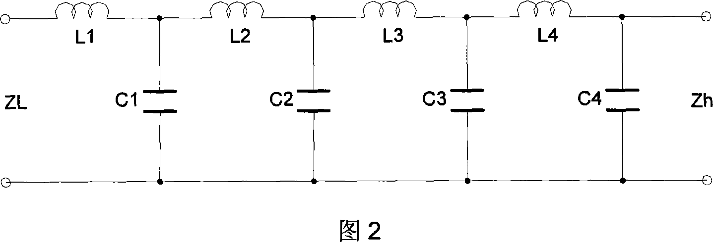
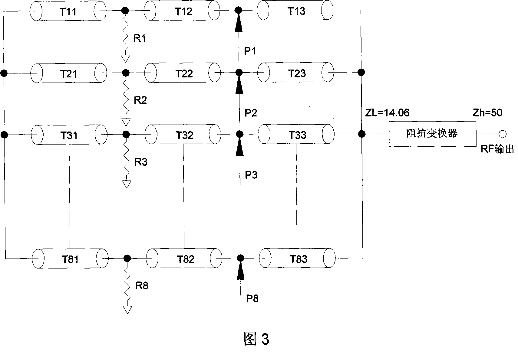
[0018] We need to design an 8-channel synthesizer used in an FM broadcast transmitter, the operating frequency range is 88-108MHz, the schematic block diagram is shown in Figure 3, and the power capacity is > 10KW; the function that needs to be completed by the impedance converter is: to convert the impedance Z L = 14.06Ω transformed to Z H =50Ω, and the ability to suppress the second and above harmonics exceeds 35dB. We can do this by:
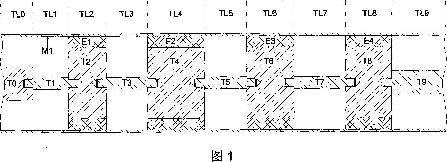
[0019] The coaxial structure shown in Figure 1 is adopted, the outer conductor M1 is a copper tube with an outer diameter of 79.4mm, the inner conductors T1~T8 are made of copper or aluminum, and the insulating support sheets E1~E4 are made of polytetrafluoroethylene. ε r =2.1; Adjacent inner conductors are connected by "threaded connection", such as T1 and T2, T2 and T3, T3 and T4...etc. in the figure.
[0020] Transmission ...
PUM
 Abstract
Description
Claims
Application Information
 - R&D
- Intellectual Property
- Life Sciences
- Materials
- Tech Scout
- Unparalleled Data Quality
- Higher Quality Content
- 60% Fewer Hallucinations
Browse by: Latest US Patents, China's latest patents, Technical Efficacy Thesaurus, Application Domain, Technology Topic, Popular Technical Reports.
© 2025 PatSnap. All rights reserved.Legal|Privacy policy|Modern Slavery Act Transparency Statement|Sitemap|About US| Contact US: help@patsnap.com


