Electricity-heated defrosting evaporator

An evaporator and electric heating wire technology, applied in the field of automatic frosting devices, can solve problems such as incomplete, unstable work, and failure of the refrigeration system to defrost

Inactive Publication Date: 2007-10-24
北京华能共发低温科技有限责任公司
View PDF0 Cites 6 Cited by
  • Summary
  • Abstract
  • Description
  • Claims
  • Application Information

AI Technical Summary

Problems solved by technology

The above three forms have their own disadvantages. For example, when opening the cold storage door to defrost, all the items in the storage must be taken out. Mechanical defrosting is easy to damage the exh...

Method used


Image

  • Electricity-heated defrosting evaporator
  • Electricity-heated defrosting evaporator

Examples


Embodiment Construction

[0009] Below in conjunction with accompanying drawing and embodiment of the present invention, further describe in detail:

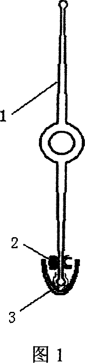
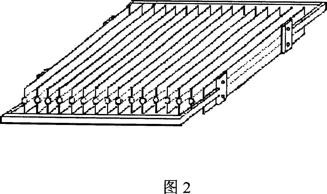
[0010] As shown in Figure 1, it consists of a double-groove finned tube 1, a heating wire 2, and a U-shaped plastic water tray 3. The double-groove fin tube 1 is formed by integral die-casting of aluminum alloy; the U-shaped plastic water tray 3 is formed by extrusion of plastic. The central opening of the U-shaped plastic water tray is plugged in on the fins of the aluminum alloy fin tube, and the heating wire is installed in the double grooves of the fins 28 . Figure 2 is composed of multiple finned tubes arranged in parallel to form a cold row, that is, an aluminum alloy evaporator. The fins of the finned tubes form a 90-degree angle with the horizontal direction. There are concave grooves on both sides of each finned tube, and the heating wire It is installed in a concave groove, and each finned tube is equipped with a U-shaped plastic water tray, a...


PUM


Abstract

Disclosed is an electro thermal evaporator for realizing cold composition defrosting, which comprises an aluminum alloy flap tube, electric heating wires and a water collection disc, each of the flap tube is provided with a groove for mounting the electric heating wires and the water collection disc.

Description

technical field [0001] The invention relates to an automatic defrosting device using the principle of electric heating, which is installed on the energy-saving aluminum alloy fin tube evaporator in the refrigeration equipment of the cold storage, so that the fin tube evaporator for the cold storage has the function of electric heating automatic defrosting, safe and reliable, and the evaporation The evaporator includes a finned tube evaporator, an electric heating wire fixed in the groove of the fixed finned tube evaporator, and a plastic drain pan below. The water after defrosting flows into the drain pan through the sink, and finally flows out of the storage. Background technique [0002] At present, the evaporator in the cold storage mainly has two forms: the air cooler and the cold exhaust pipe. [0003] The traditional cold row tube evaporator has more advantages than the air cooler during the use of the cold storage, such as high air humidity in the cold storage, less f...

Claims


Application Information

Patent Timeline
IPC IPC(8): F25B39/02F25B47/00
Inventor 史玉成
Owner 北京华能共发低温科技有限责任公司
Why Eureka
Try Eureka