
A self-protective lead-acid storage battery and its manufacture method

The technology of a lead-acid battery and its manufacturing method is applied in the directions of lead-acid battery, lead-acid battery construction, battery pack components, etc., which can solve the problems of lead-acid battery damage, damage, gas evolution, etc., so as to improve the service life, Simple structure, prolong normal effect

Inactive Publication Date: 2007-10-24
周海
View PDF0 Cites 2 Cited by
  • Summary
  • Abstract
  • Description
  • Claims
  • Application Information

AI Technical Summary

Problems solved by technology

Due to the complex manufacturing process of the grid and coating active material of the lead-acid battery (for example: the curing and drying process has very strict process requirements for the control of humidity and temperature), it is difficult to ensure that the positive and negative electrodes inside the lead-acid battery The consistency of the grid leads to certain differences in capacity and internal resistance between each pair of positive and negative plates inside the lead-acid battery.
Due to the existence of this difference, such as: the capacity between a certain pair of positive and negative plates is too small or the internal resistance is too high, when the lead-acid battery is charged, the voltage of the pair of positive and negative plates will inevitably increase. The voltage is too high, so that the adjacent positive and negative grid pairs reach the limit voltage earlier. If there is no limit at this time, the voltage will continue to rise, resulting in overcharging, and overcharging will cause a sharp rise in temperature and gas evolution. Too much water loss (electrolyte loss) due to increase in size may lead to deformation of the positive and negative grids on the one hand, and lower capacity on the other hand
Over and over again, the rate of water loss is accelerated, and a vicious circle will appear during the cycle charging process, so that the pair of positive and negative grids will be damaged in advance due to excessive water loss, and then the adjacent positive and negative grid pairs will also be damaged due to excessive water loss. Overcharging causes heat out of control, water loss, etc.
[0004] Due to the above reasons, the service life of the entire lead-acid battery is greatly shortened!

Method used


Image

  • A self-protective lead-acid storage battery and its manufacture method
  • A self-protective lead-acid storage battery and its manufacture method
  • A self-protective lead-acid storage battery and its manufacture method

Examples


Embodiment Construction

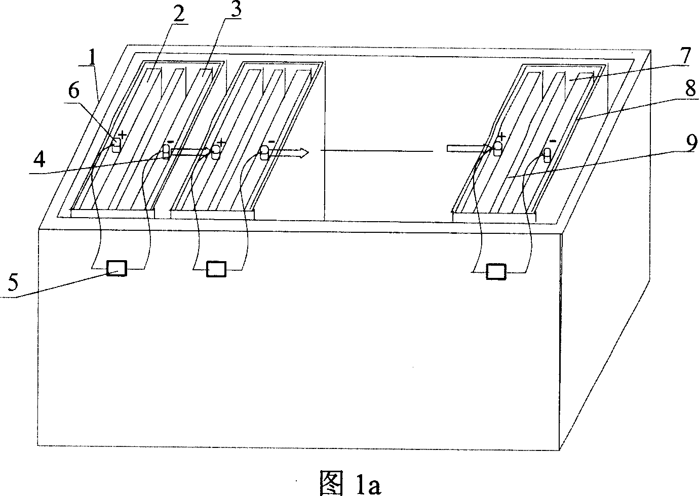
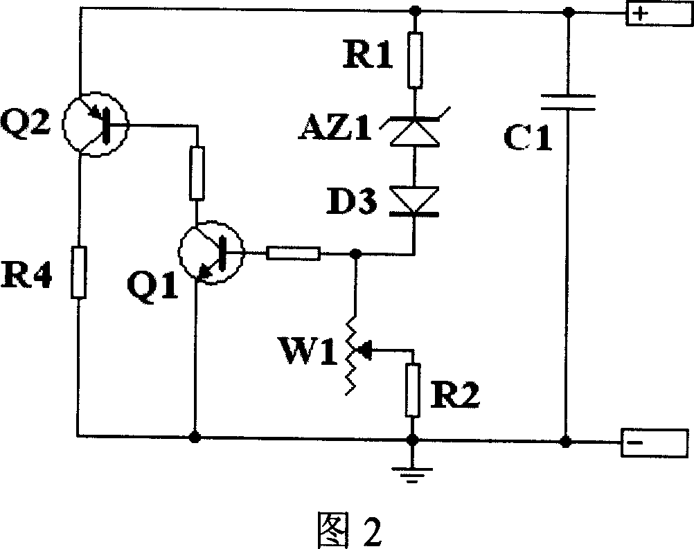
[0027] As shown in Fig. 1a and Fig. 2, a kind of self-protection lead-acid battery, lead-acid battery comprises housing 1, is provided with a plurality of battery units 7 in housing 1, and each battery unit 7 is made of a pole for containing electrolyte The plate groove 8, the positive grid 2, the separator 9 and the negative grid 3 are composed. There is a positive terminal 6 on the positive grid 2, a negative terminal 4 on the negative grid 3, a separator 9 is arranged between the positive grid 2 and the negative grid 3, and the positive grid in each plate groove 8 2 and the negative grid 3 form a positive and negative grid pair. The negative terminal 4 of the previous pair of positive and negative grids is electrically connected to the positive terminal 6 of the next pair of positive and negative grids, and connected in sequence to form a lead-acid battery in series. A bypass circuit 5 for shunting the positive and negative grid pairs (2, 3) when charging is connected in p...


PUM


Abstract

The disclosed preparation method for self-shielded lead-acid battery comprises: (1) setting in turns the positive plate, baffle plate and the negative plate in different shell slots, and connecting the negative plate with the next positive plate serially; and (2) paralleling at least one by-pass circuit between every positive and negative plates for shunting during charging when the charging voltage up to near or up to a threshold. This invention can prevent the over-charge or less-charge, and improves the service time of lead-acid battery greatly.

Description

technical field [0001] The invention relates to a lead-acid battery and its manufacturing technology. Background technique [0002] Lead-acid batteries have experienced more than a century of history. Due to their continuous power capabilities, they have been widely used as various power sources in various industries such as automobiles, ships, and electric vehicles. [0003] The grid is an important part of the lead-acid battery. The grid includes the positive and negative grids. Its role in the lead-acid battery is mainly to support the active material. Usually, a packaged lead-acid battery is often composed of many or even tens of pairs of positive and negative grids coated with active materials connected in series. Due to the complex manufacturing process of the grid and coating active material of the lead-acid battery (for example: the curing and drying process has very strict process requirements for the control of humidity and temperature), it is difficult to ensure ...

Claims


Application Information

Patent Timeline
Patent Type & Authority Applications(China)
IPC IPC(8): H01M10/12H01M2/34H01M50/572
CPCY02E60/126Y02E60/10Y02P70/50
Inventor 周海
Owner 周海
Learn More