
Compact cantilever rolling mill and a method of producing a metallic product

一种金属制品、轧机的技术,应用在轧机领域,能够解决支撑辊受力高、角度不合适、悬臂式轧机不能操控轧制力等问题

Inactive Publication Date: 2007-10-24
LUVATA OY
View PDF3 Cites 2 Cited by
  • Summary
  • Abstract
  • Description
  • Claims
  • Application Information

AI Technical Summary

Problems solved by technology

However, even with such a solution, the forces on the back-up rolls are very high due to the inappropriate angle at which the rolling force is transmitted to the back-up rolls
[0007] Despite stronger bearings and other described solutions, the cantilever mill still cannot handle the same high rolling forces as a standard mill

Method used


Image

  • Compact cantilever rolling mill and a method of producing a metallic product
  • Compact cantilever rolling mill and a method of producing a metallic product
  • Compact cantilever rolling mill and a method of producing a metallic product

Examples


Embodiment Construction

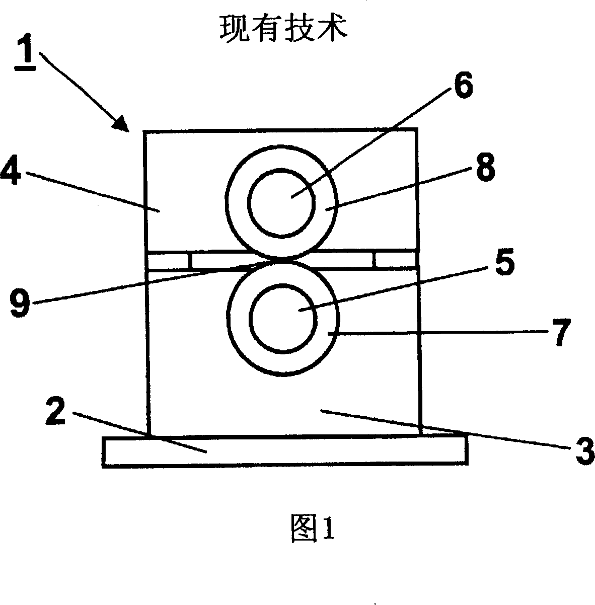
[0021] Figure 1 is a simplified representation of the components of a typical cantilever rolling mill 1 according to the prior art. The rolling mill 1 comprises a base 2 supporting a lower roll housing 3 . The lower roll frame 3 supports the upper roll frame 4 . A lower roll shaft 5 and an upper roll shaft 6 are mounted on the roll stands 3 and 4 . Mounted on the roller shafts 5 and 6 are ring rollers 7 and 8 between which a nip 9 is formed.

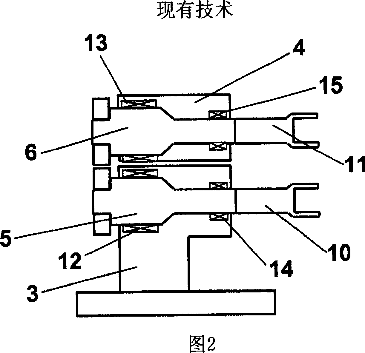
[0022] FIG. 2 is another view of the prior art cantilever rolling mill of FIG. 1. FIG. The roll shafts 5 and 6 respectively have drive ends 10 and 11 at the ends for driving the rolling mill with a drive motor. The roll shafts 5 and 6 are mounted on the roll frames 3 and 4 by heavy main bearing assemblies 12 and 13 and lighter bearing assemblies 14 and 15 which are located closer to the drive ends 10 and 11 of the roll shafts. The heavy main bearing assemblies 12 and 13 carry the major part of the rolling forces. The lighter bearing...


PUM


Abstract

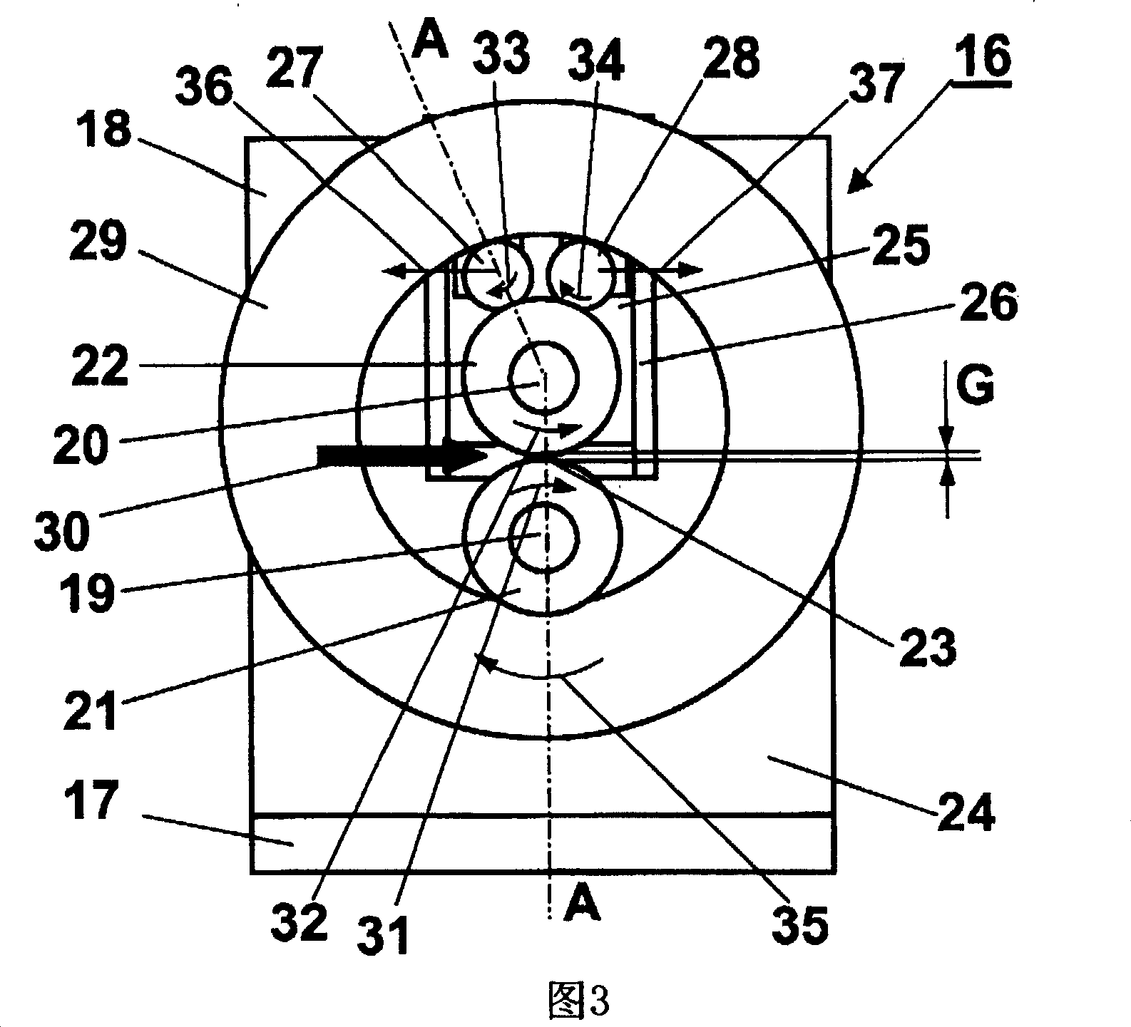
The invention relates to an apparatus for rolling a metallic product comprising a mill frame ( 18 ), a first cantilever roll shaft ( 19 ), a second cantilever roll shaft ( 20 ), both said roll shafts ( 19, 20 ) being mounted on the mill frame ( 18 ) with two sets of bearing assemblies ( 38, 39, 40, 41 ), a first rolling ring ( 21 ) mounted on the first roll shaft ( 19 ), a second rolling ring ( 22 ) mounted on the second roll shaft ( 20 ) said rolling rings ( 21, 22 ) forming a nip ( 23 ) in between, at least one ring ( 29 ) arranged with its inside surface ( 43 ) in rolling contact with the first roll shaft ( 19 ) and with at least one intermediate roll ( 27 ), which intermediate roll ( 27 ) is arranged also in rolling contact with the second roll shaft ( 20 ) and at least one drive end ( 42 ) arranged at the end of either roll shafts ( 19, 20 ) for driving the mill ( 16 ). The invention also relates to a method of producing a metallic product.

Description

Background technique [0001] The present invention generally relates to rolling mills for rolling metal products such as cables, strips, wires and profiles. More particularly, the present invention relates to a compact size cantilever device for rolling metal materials and a method of manufacturing metal products. [0002] Rolling mills are used to reduce thickness and shape metal products. There are two types of mills. In the first type of rolling mill, the work rolls have solid support bearings at their ends, which connect the work rolls to the roll stands, which cover the whole rolling mill. This type is called a "standard" mill. Another type of mill is called a cantilever mill, in which the actual rolling occurs outside the roll frame and the work rings are fitted to the roll shafts which are only passed by the roll frame from the other side of the nip support. The term "nip" is used herein to refer to the closest area of ​​the work rolls or rolling rings. [0003] Th...

Claims


Application Information

Patent Timeline
Patent Type & Authority Applications(China)
IPC IPC(8): B21B29/00B21B13/00B21B13/14B21B31/02B21B31/16
CPCB21B29/00B21B31/02B21B13/005B21B31/16
Inventor 伊尔波·科皮宁斯旺克·布赖恩汉斯·凯弗
Owner LUVATA OY
Learn More