Method for performing a magnetic pulse welding operation to secure first and second metallic components with a preheating step for softening a first part of the first member

A metal part, magnetic pulse technology, applied in the connection between the superstructure sub-assemblies, metal processing, welding equipment, etc., can solve the problems of deformation, weakening, component failure and other problems of metal parts

Inactive Publication Date: 2007-10-31
DANA AUTOMOTIVE SYST GRP LLC
View PDF4 Cites 9 Cited by
  • Summary
  • Abstract
  • Description
  • Claims
  • Application Information

AI Technical Summary

Problems solved by technology

Such heating can cause undesirable deformation and weakening of metal parts
Second, although conventional welding techniques are suitable for joining together parts made of similar metallic materials, they have been found to be difficult to use to join parts made of dissimilar metallic materials
Third, traditional welding techniques are not easy to adapt to the connection of components with different standard thicknesses
Unbalanced centrifugal force proportional to the square of the rotational speed promotes deflection, stress and vibration, which can lead to component failure, annoying noise, and discomfort for vehicle occupants

Method used


Image

  • Method for performing a magnetic pulse welding operation to secure first and second metallic components with a preheating step for softening a first part of the first member
  • Method for performing a magnetic pulse welding operation to secure first and second metallic components with a preheating step for softening a first part of the first member
  • Method for performing a magnetic pulse welding operation to secure first and second metallic components with a preheating step for softening a first part of the first member

Examples


Embodiment Construction

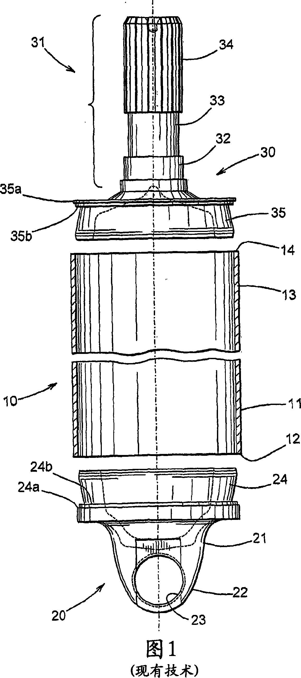
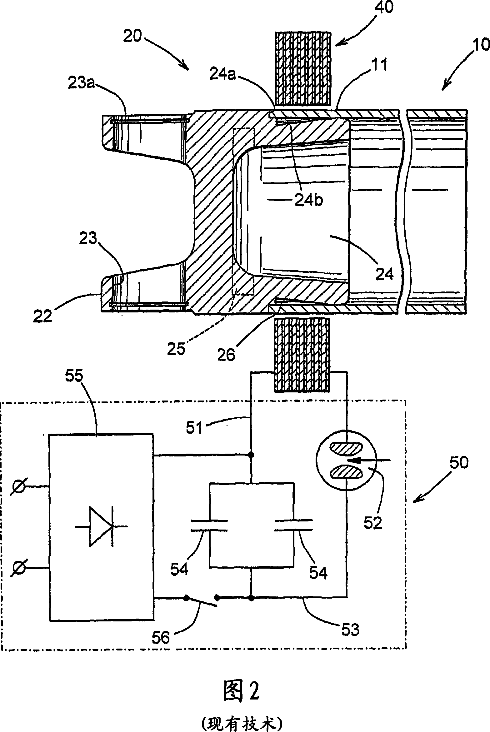
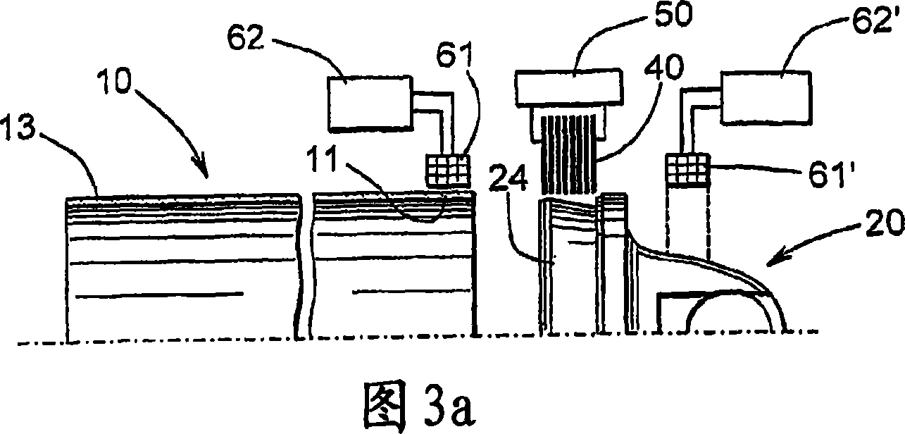
[0020] Referring now to the drawings, as shown in FIGS. 1 and 2 , there is shown a drive shaft tube 10 , a first end fitting, such as a shaft tube yoke 20 , and a second end fitting, such as a tube shaft 30 . While the present invention has been described and illustrated in the context of securing the first and second end fittings 20 and 30 to the propshaft tube 10 to form at least a portion of the propshaft assembly, it will be appreciated that for any desired Regardless of purpose or application, the method described in this invention can be used to secure any two metal parts together.

[0021] The illustrated transmission shaft tube 10 is generally hollow and cylindrical in shape, and it can be made of any desired metal material, such as 6061-T6 aluminum alloy. Preferably, drive shaft tube 10 has outer and inner surfaces that define substantially constant outer and inner diameters. Accordingly, the illustrated driveshaft tube 10 has a substantially cylindrical shape and a ...


PUM

PropertyMeasurementUnit
diameteraaaaaaaaaa
thicknessaaaaaaaaaa
yield strengthaaaaaaaaaa

Abstract

A method of performing magnetic pulse welding operation to secure first and second metallic components (10, 20) together involves initially increasing the temperature of a first portion (11) of the first metallic component to soften same without substantially increasing the temperature of and softening a second portion of the first metallic component adjacent to the first portion (11). Then, the first portion (11) of the first metallic component (10) is disposed in an axially overlapping manner relative to a portion of the second metallic component (20) with a space therebetween. An inductor (40) is provided relative to the axially overlapping portions of the first and second metallic components (10, 20). The inductor (40) is energized to deform the first portion (11) of the first metallic component (10) into engagement with the portion of the second metallic component (20) so as to secure the first and second metallic components (10, 20) together.

Description

technical field [0001] The present invention generally relates to magnetic pulse welding techniques for securing two metal parts together. More particularly it relates to an improved method of performing the above-mentioned magnetic pulse welding operation which minimizes the amount of undesired deformation which would occur in said one or both metal parts. Background technique [0002] In most land vehicles today there is a driveline system for transferring rotational force from the output shaft of the engine / transmission assembly to the input shaft of the transaxle assembly to rotatably drive one or more wheels of the vehicle. To accomplish this, a typical vehicle driveline assembly includes a cylindrical propshaft tube having first and second end fittings secured at opposite ends thereof. The first end fitting forms part of the first universal joint which provides a rotatable drive connection from the output shaft of the engine / transmission assembly to the first end of t...

Claims


Application Information

Patent Timeline
Patent Type & Authority Applications(China)
IPC IPC(8): B23K20/06B62D27/02F16D1/072F16C3/02
CPCB23K13/015B23K2201/006B23K2201/04B23K20/06F16C3/02B23K2201/06F16D1/068H01F38/085F16D1/072B23K2203/10B23K2101/006B23K2101/04B23K2101/06B23K2103/10F16C3/023F16C2226/36
Inventor B·A·亚布洛奇尼科夫
Owner DANA AUTOMOTIVE SYST GRP LLC
Why Eureka
Try Eureka