
Energy conversion apparatus

a technology of energy conversion apparatus and energy conversion, which is applied in the direction of electric variable regulation, process and machine control, instruments, etc., can solve the problems of limiting complicated circuit structure for implementing energy conversion, and increasing the size of energy harvesting apparatus, so as to achieve the effect of maximizing the efficiency of energy conversion

Inactive Publication Date: 2014-06-12
ELECTRONICS & TELECOMM RES INST
View PDF6 Cites 241 Cited by
  • Summary
  • Abstract
  • Description
  • Claims
  • Application Information

AI Technical Summary

Benefits of technology

Example embodiments of the present invention provide a device that can convert energy easily and with high efficiency.

Problems solved by technology

As described above, since the conventional energy converter uses two DC-to-DC converters, there is a problem that a constitution of circuit for implementing the energy converter should be complicated and the size of the energy harvesting apparatus should increase.
Also, since two DC-to-DC conversions are performed in a procedure of energy conversion, energy losses can be occurred two times so that there is a limit to enhance energy conversion efficiency.

Method used


Image

  • Energy conversion apparatus
  • Energy conversion apparatus
  • Energy conversion apparatus

Examples


Embodiment Construction

[0027]Example embodiments of the present invention are disclosed herein. However, specific structural and functional details disclosed herein are merely representative for purposes of describing example embodiments of the present invention, however, example embodiments of the present invention may be embodied in many alternate forms and should not be construed as limited to example embodiments of the present invention set forth herein.

[0028]Accordingly, while the invention is susceptible to various modifications and alternative forms, specific embodiments thereof are shown by way of example in the drawings and will herein be described in detail. It should be understood, however, that there is no intent to limit the invention to the particular forms disclosed, but on the contrary, the invention is to cover all modifications, equivalents, and alternatives falling within the spirit and scope of the invention Like numbers refer to like elements throughout the description of the figures....


PUM


Abstract

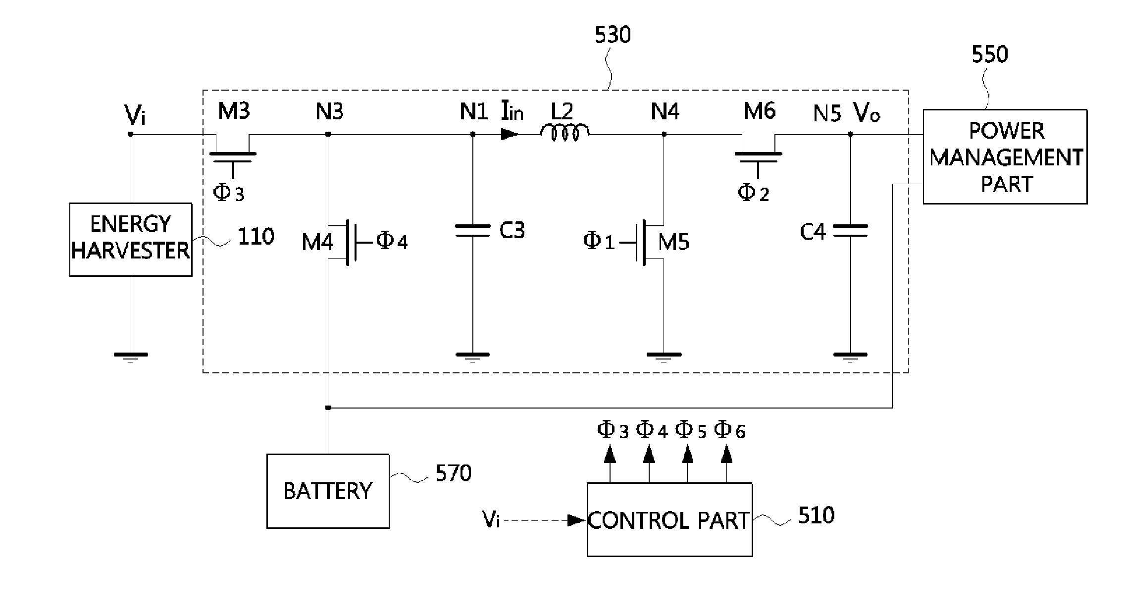
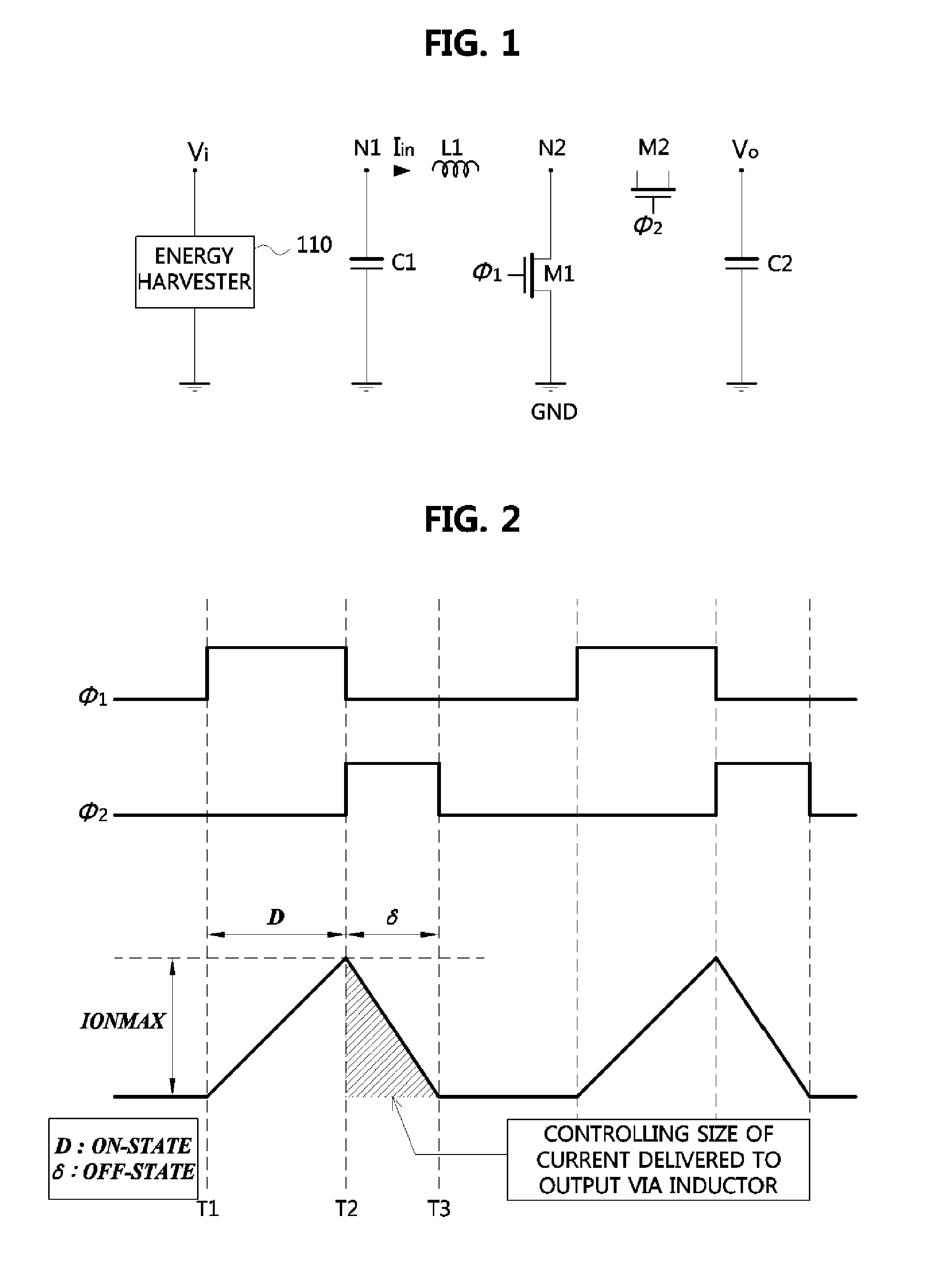
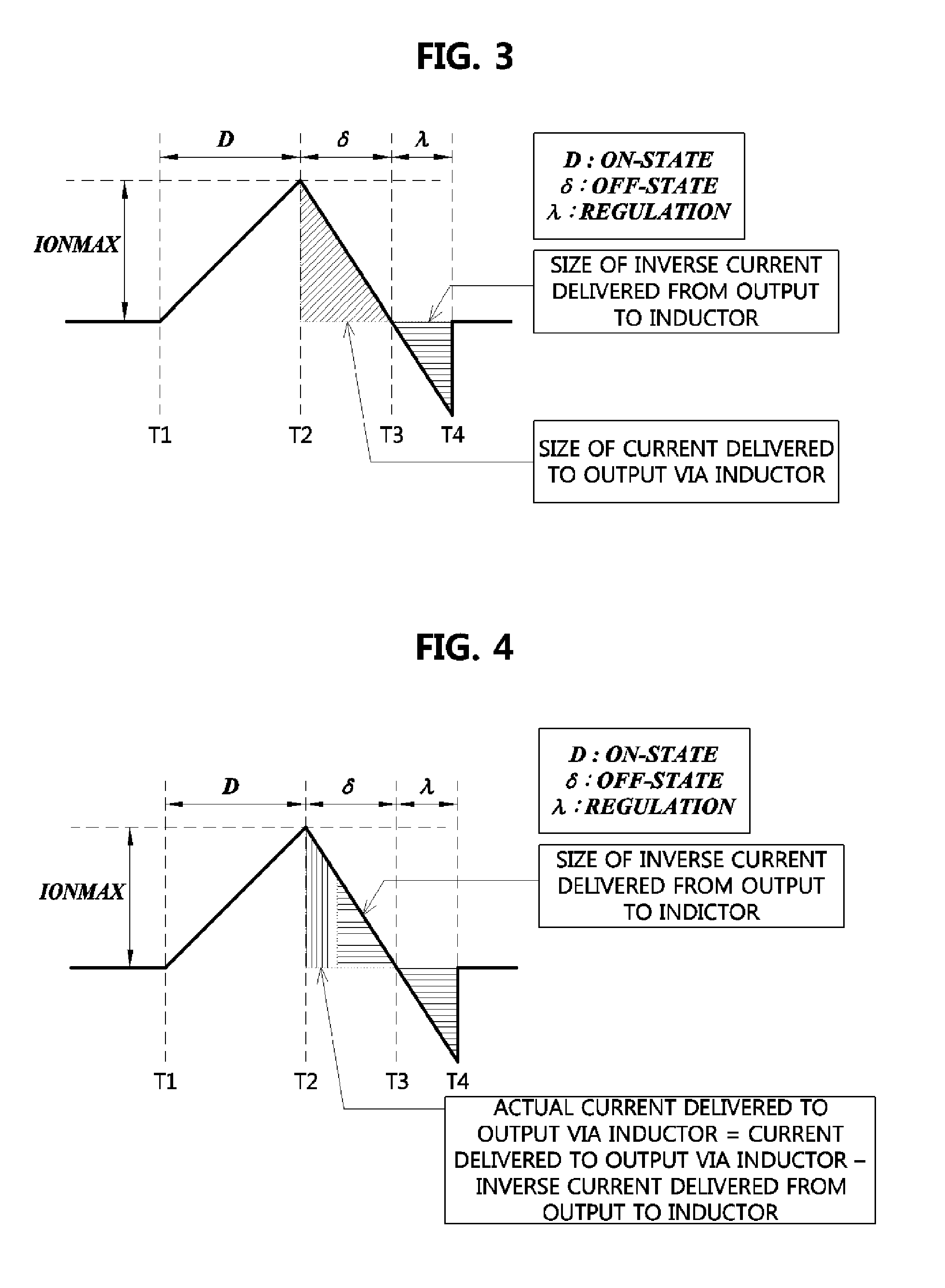
Disclosed is an energy conversion apparatus. An energy conversion apparatus may comprise a control part controlling a length of a first time duration in which input current is inputted and accumulated, a length of a second time duration in which the accumulated current is provided to a load, and a length of a third time duration in which inverse current flows; and a DC-to-DC converter including an inductor, a output capacitor, and at least one switching element, wherein the input current is accumulated during the first time duration by switching the at least one switching element according to a control of the control part so as to perform input impedance matching, and the DC-to-DC convert provides a current corresponding to a difference between the accumulated current provided during the second time duration and the inverse current flowing from the output capacitor during the third time duration to the load.

Description

CLAIM FOR PRIORITY[0001]This application claims priorities to Korean Patent Application No. 10-2012-0142962 filed on Dec. 10, 2012 in the Korean Intellectual Property Office (KIPO), the entire contents of which are hereby incorporated by references.BACKGROUND[0002]1. Technical Field[0003]Example embodiments of the present invention relate to a technology of converting energy, and more specifically to an energy conversion apparatus which can achieve high conversion efficiency with a simple configuration.[0004]2. Related Art[0005]A technology of energy harvesting is a technology for harvesting circumjacent energy thrown away, converting it to usable energy, and storing the usable energy for later use. The technology may enhance energy performance of electric devices and the like, and make it possible to drive electric devices by using circumjacent energy without any additional energy supplied.[0006]As examples of energy harvesting technologies, there are a sunlight generation using su...

Claims


Application Information

Patent Timeline
IPC IPC(8): H02M3/155H02J7/00
CPCH02M3/158H02J7/32H02J7/0068H02J2207/20H02J50/001H02M3/155H02J50/10
Inventor KIM, SUNG EUNKANG, TAE WOOKPARK, KYUNG HWANKANG, SUNG WEONCHUNG, MYUNG AE
Owner ELECTRONICS & TELECOMM RES INST
Learn More