Cylinder driving apparatus using air pressure

a technology of driving apparatus and cylinder, which is applied in the direction of positive displacement engines, flexible wall reciprocating engines, and engines characterised by uniflow principles, etc., can solve the problems of fissil energy source running out, and achieve the effects of reliable rotational movement, improved energy efficiency, and maximizing the efficiency of energy conversion

Active Publication Date: 2011-09-08
HA SEOK BONG
View PDF3 Cites 0 Cited by
  • Summary
  • Abstract
  • Description
  • Claims
  • Application Information

AI Technical Summary

Benefits of technology

[0008]According to the present invention, a connecting rod fixed at each of a plurality of flexible tubes is connected to a crank shaft, thus obtaining a reliable rotational movement, and the flexible tubes filled with compressed air expand and elevate with the aid of air injection of high pressure air by the descending force of other flexible tubes and the compression force of the assistant tubes, so the expansion energy of air generating in the plurality of the flexible tubes serves to rotate the crank shaft with the aid of inter-operations, thus maximizing the efficiency of energy conversion.
[0009]The improvement of the energy efficiency helps reduce fossil energy, which results in the protection of environment along with the application as clean energy with the aid of increased use of compressed air energy, thus obtaining a large effect in energy field. The present invention might serve to provide a large value as alternative energy and exchangeable energy resource.
[0010]In the conventional art, driving source is obtained using various fossil fuels, but the present invention makes it possible to provide environmentally friendly new energy resource to mankind along with obtaining stable life and economical developments while terminating energy problems due to high oil price, and the present invention might help change to all conventional energy sources or substitute the same.

Problems solved by technology

However, the fossil energy source runs out because the amount of fossil energy is very limited in nature and serves to contaminate environment when in use.

Method used


Image

  • Cylinder driving apparatus using air pressure
  • Cylinder driving apparatus using air pressure
  • Cylinder driving apparatus using air pressure

Examples


Embodiment Construction

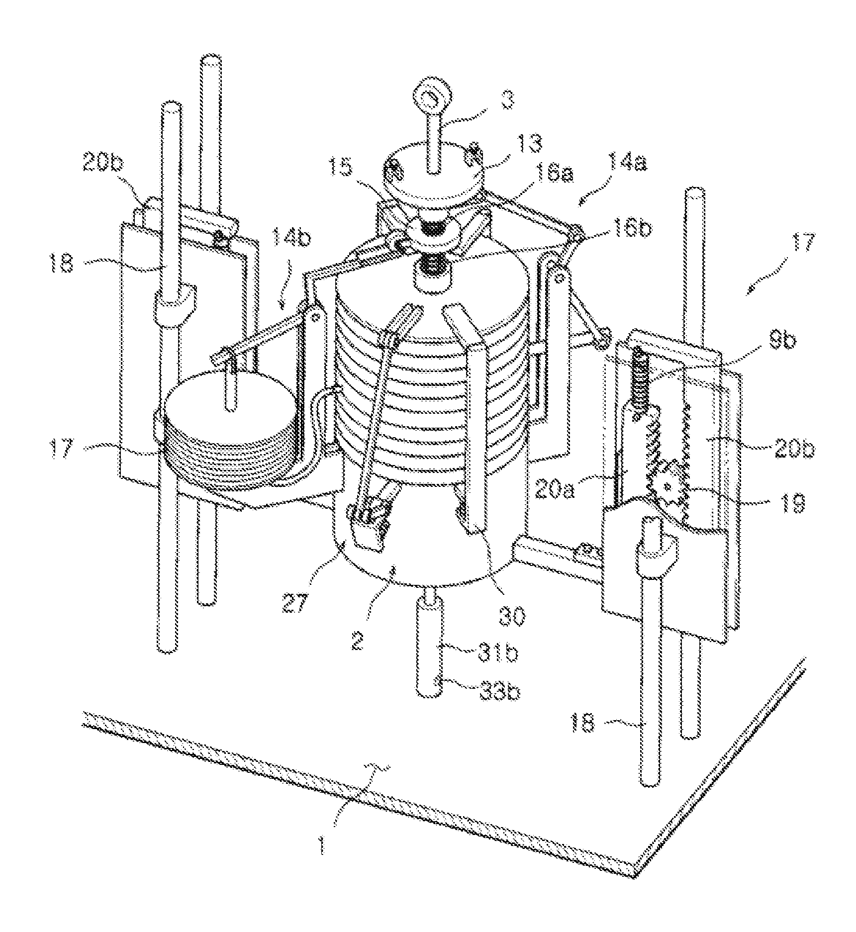
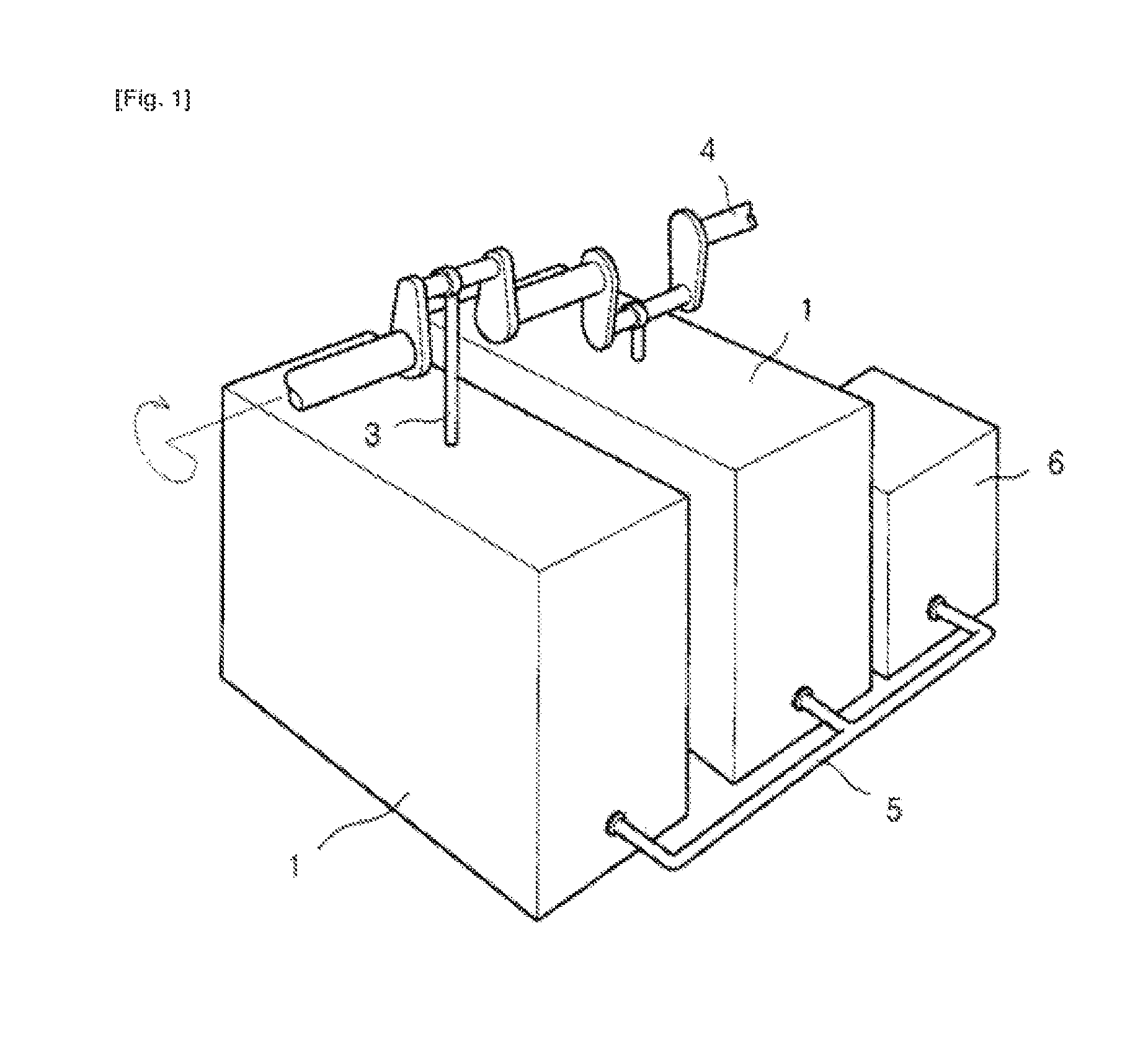
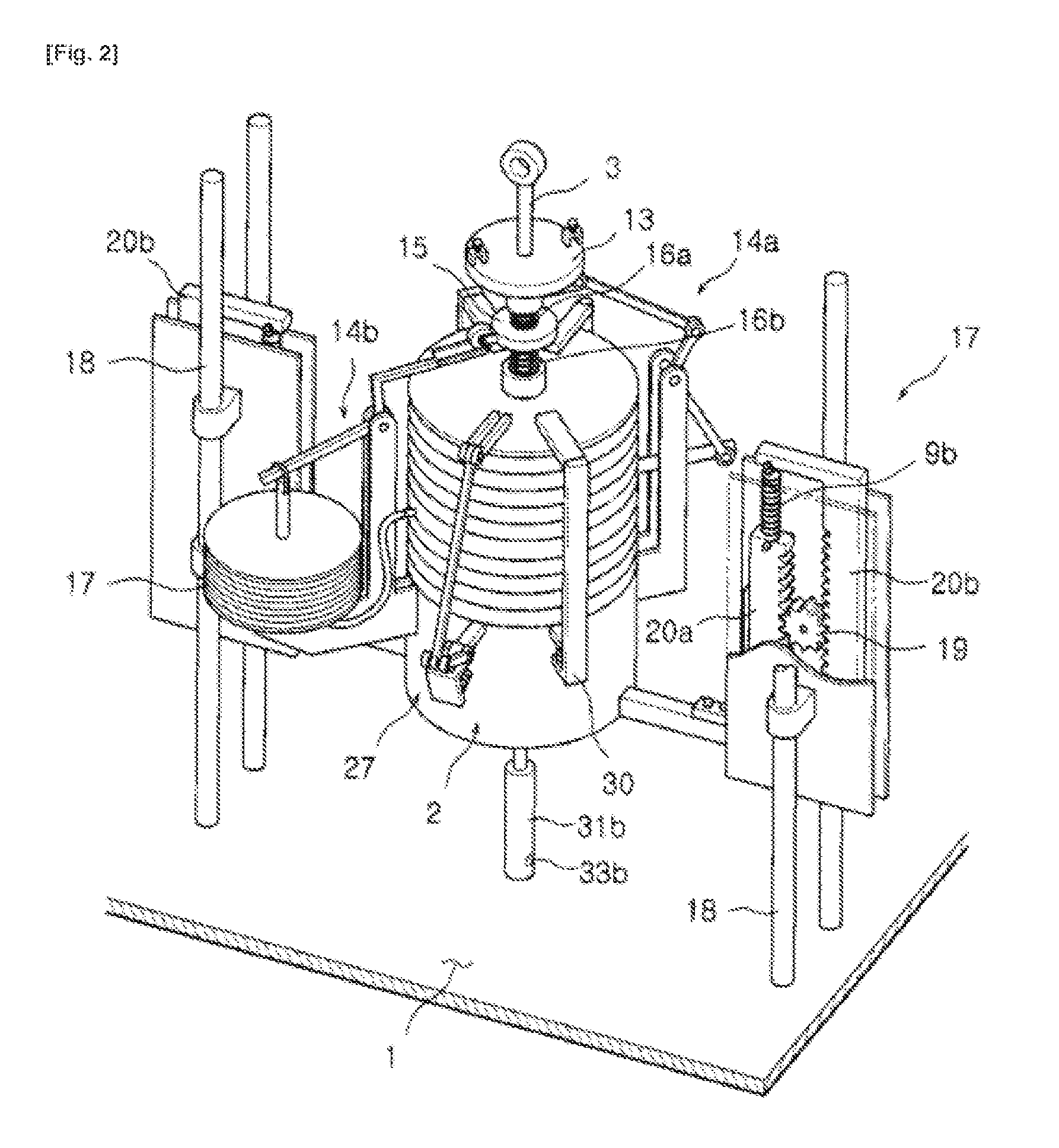
[0052]The cylinder driving apparatus using air pressure according to the present invention is directed to improving the constructions consisting of a plurality of flexible tubes 2 installed in the interior of a casing 1 and being flexible with the aid of high pressure air, a connecting rod 3 which is fixed each flexible tube 2 and passes through the upper side of the casing 1, a crank shaft which is sequentially engaged to the connecting rod 3 and rotates with the aid of an elevation operation of the connecting rod 3, and a high pressure tank 6 supplying high pressure air to the flexible tube 2 via an air line 5.

[0053]Namely, the present invention is directed to more efficiently utilizing the expansion energy of compression air by providing a flexible tube 2 and an assistant tube 7 of FIGS. 2 to 4.

[0054]As shown in FIG. 3, in case of the flexible tube 2, there are provided a valve 8 which is installed partitioning the interior of the flexible tube 2 into upper and lower spaces, thus...


PUM


Abstract

It is an aim of the present invention to overcome urgent and pressing global troubles directly associated with the human right to live, such as the energy crisis, the economic crisis, and environmental pollution and the like which cannot be delayed or neglected any longer in order to meet the needs of the times. Further, it is an aim of the present invention to significantly reduce the dependency on a variety of fossil directly associated with global warming. Therefore, the present invention provides a cylinder driving apparatus using air pressure, with maximized energy, characterized in that the use of fossil fuel energy is reduced and the use of clean energy is proposed. The present invention relates to a cylinder diving apparatus in which a plurality of flexible tubes connected to a crankshaft are filled with high pressure air, alternately expand by expansion energy, and are elevated to operate and rotate the crankshaft. Further, the preset invention relates to an apparatus for minimizing friction and eliminating gravitational force which may interfere with the elevating movement, to thereby maximize the efficiency of the conversion of compressed air expansion energy into rotating movement. The present invention achieves a great and active supplement and improvement over Korean Patent Registration No. 0041791 and No. 0210368 granted to the applicant of the present invention, ad proposes an inventive structure of an assistant tube that provides a novel energy source. Conventional apparatus use a variety of fossil fuels as a power source, whereas the present invention eliminates the repeated rise of oil prices ad ends energy problems, enables people to enjoy a stable life and aids in economic development, and provides all mankind with a new environmentally-friendly energy resource to take the place of the innumerable conventional power sources. The cylinder driving apparatus using air pressure according to the present invention comprises: a plurality of flexible tubes arranged in a case to flexibly move via high-pressure air; a connecting rod fixed at each f the flexible tubes, and which penetrates through an upper portion of the case; a crank shaft sequentially coupled to the connecting rod to rotate via the elevating movement of the connecting rod; a high pressure tank for supplying high pressure air to the flexible tubes via an air line; and a valve arranged in each of the flexible tubes to divide the space in the flexible tube into an upper section and a lower section and to open/shut airflow in the upper and lower sections. The valve is shut to block the upper and lower sections from each other when the flexible tubes are filled with high pressure air, and opens when the flexible tubes are elevated to top center. The valve is connected to an assistant tube, the interior of which is equipped with a tensile spring force to keep the assistant tube compressed, to enable compressed air in the flexible tubes to flow to the assistant tube when the valve opens.

Description

TECHNICAL FIELD[0001]The present invention relates to a cylinder driving apparatus using air pressure, and in particular to a cylinder driving apparatus using air pressure which a plurality of expansion tubes each connected to a crank shaft are filled with high pressure air and are alternately expanded by means of expansion energy and elevate, thus obtaining a rotational force by driving a crank shaft, and friction can be minimized, and gravitational force generated by self-weight can be offset, which force might interfere with an elevating movement, thus maximizing the efficiency that expansion energy of compressed air is converted into rotational movement.BACKGROUND ART[0002][Relevant reference 1] Korean patent registration number 0041791, May 15, 1991[0003][Relevant reference 2] Korean patent registration number 0210368, Apr. 26, 1999[0004]Conventional motor is driven by fossil energy such as gasoline, coal, gas, etc. the reciprocation movement of a piston of which generated by m...

Claims


Application Information

Patent Timeline
Patent Type & Authority Applications(United States)
IPC IPC(8): F01B11/00
CPCF01B19/04F01B17/02F01B1/10F01B11/00F03C1/00
Inventor HA, SEOK-BONG
Owner HA SEOK BONG
Why Eureka
Try Eureka