Apparatus method for wet treatment of wafers

A technology for wet processing and equipment, used in electrical components, semiconductor/solid-state device manufacturing, circuits, etc.

Inactive Publication Date: 2011-07-06
LAM RES AG
View PDF3 Cites 0 Cited by
  • Summary
  • Abstract
  • Description
  • Claims
  • Application Information

AI Technical Summary

Problems solved by technology

[0007] An object of the present invention is to simultaneously solve the problem of wetting the center of the wafer and properly cleaning the center of the wafer

Method used


Image

  • Apparatus method for wet treatment of wafers
  • Apparatus method for wet treatment of wafers
  • Apparatus method for wet treatment of wafers

Examples


Embodiment Construction

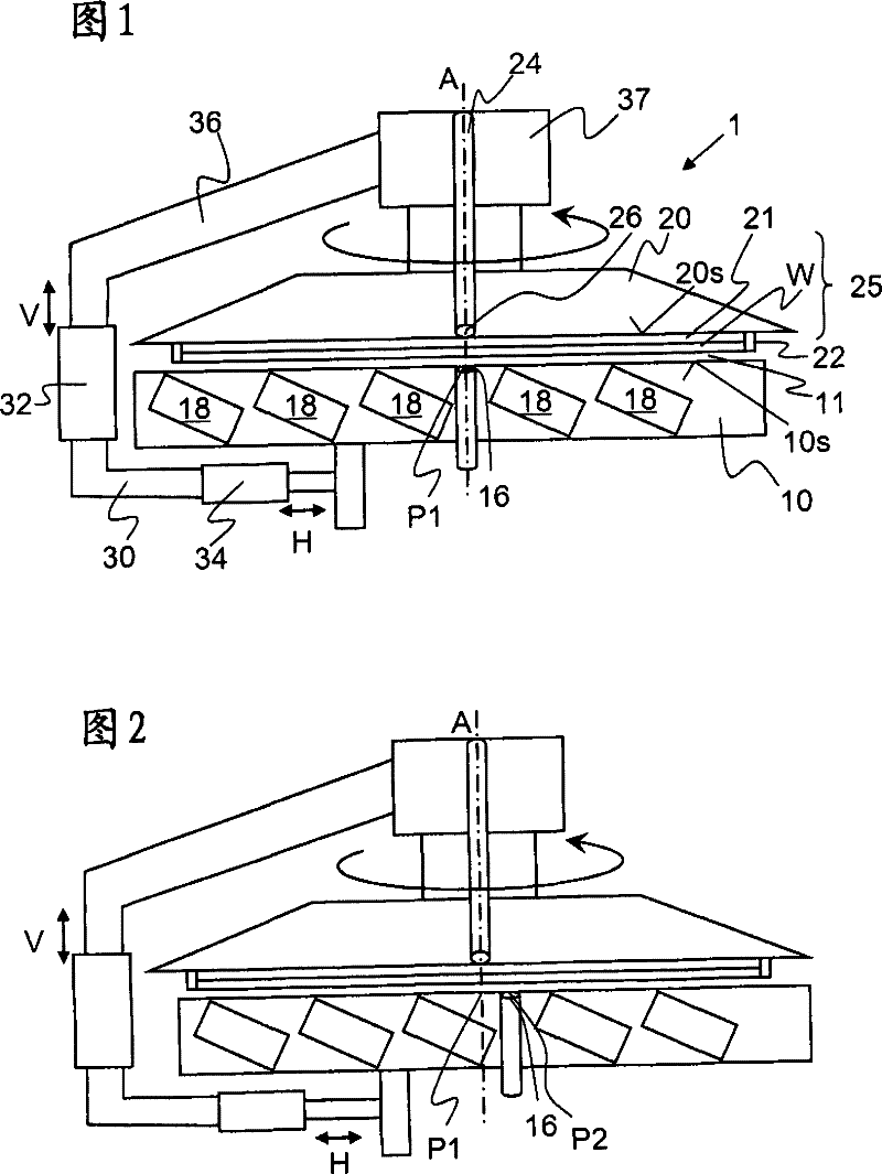
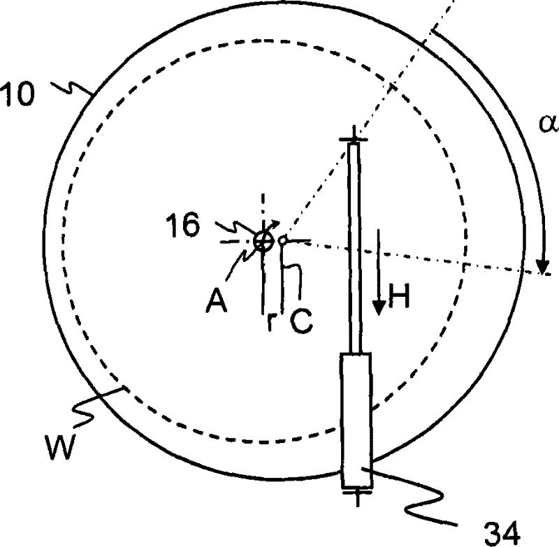
[0039] figure 1 Shown is a schematic diagram of an apparatus 1 of an embodiment of the invention.

[0040] A rotary chuck 25 for rotatably holding a wafer W is mounted in a suspended state so as to hold the wafer W thereunder. The spin chuck 25 includes gripping pins 22 for securely gripping the wafer W at the edge of the wafer. The clamp pins can be moved eccentrically or tilted for clamping and releasing the wafer W. The mechanism (not shown) for moving the clamping needle may be similar to that disclosed in US Patent No. 4,903,717. The spin chuck 25 further includes a chuck plate 20 having a flat surface 20s parallel to and overlapping a wafer being processed. The plane 20s has a dispensing opening 26 at its center for receiving a fluid nozzle. The rotary chuck 25 is mounted via a coaxial hollow shaft to a hollow shaft motor 37 . The swivel chuck 25 rotates about this hollow shaft and an axis of rotation A of the swivel chuck 25 perpendicular to the plane 20s. A tube ...


PUM


Abstract

Disclosed is a device for wet treatment of disk-like substrates comprising a first plate (10) with a size and shape being able to overlap a disk-like substrate to be treated, holding means (22) for holding a disk-like substrate (W) parallel to said first plate in a distance of 0.2 to 5 mm, rotating means (37) for rotating the disk-like substrate (W) about a rotation axis (A) substantially perpendicular to said first plate, first dispensing means (14) with a first dispensing opening (16) in the first gap for introducing fluid into a first gap (11) between said first plate (10) and a disk-like substrate (W) when being treated, and shifting means (34) for shifting the position of said first dispensing opening (16) from a first position (P1) to a second position (P2) wherein the distance of said first position (P1) to the rotation axis (A) is smaller than the distance of said second position (P2) to the rotation axis (A). Furthermore an associated method is disclosed.

Description

field of invention [0001] The invention relates to an apparatus for wet processing of disk-shaped substrates, said apparatus comprising: a first plate having a size and shape capable of overlapping a disk-shaped substrate to be processed; clamping means for clamping A disk-shaped substrate parallel to the first plate at a distance of 0.2 to 5 mm; a rotating device for rotating the disk-shaped substrate around a rotation axis substantially perpendicular to the first plate. First distributing means are provided for introducing fluid into a first gap between the first plate and a disk-shaped substrate during treatment. If the term wafer is used hereinafter, it means such a disk-shaped substrate. Background technique [0002] Such equipment will primarily be used to clean particles from the wafer surface, but may also be used to clean contaminants of ionic or organic nature. Various etching and passivation steps may be performed after the cleaning step. [0003] US Patent No....

Claims


Application Information

Patent Timeline
Patent Type & Authority Patents(China)
IPC IPC(8): H01L21/00
CPCH01L21/67051H01L21/304H01L21/687
Inventor H.奥科恩-施密特
Owner LAM RES AG
Why Eureka
Try Eureka