Eureka AIR delivers breakthrough ideas for toughest innovation challenges, trusted by R&D personnel around the world.

Variable capacity swash plate type compressor

A technology of variable capacity and compressor, applied in the direction of liquid variable capacity machinery, variable capacity pump components, mechanical equipment, etc., can solve problems such as increasing the size of compressor 1

Inactive Publication Date: 2007-11-07
HALLA CLIMATE CONTROL
View PDF0 Cites 6 Cited by
  • Summary
  • Abstract
  • Description
  • Claims
  • Application Information

AI Technical Summary

Problems solved by technology

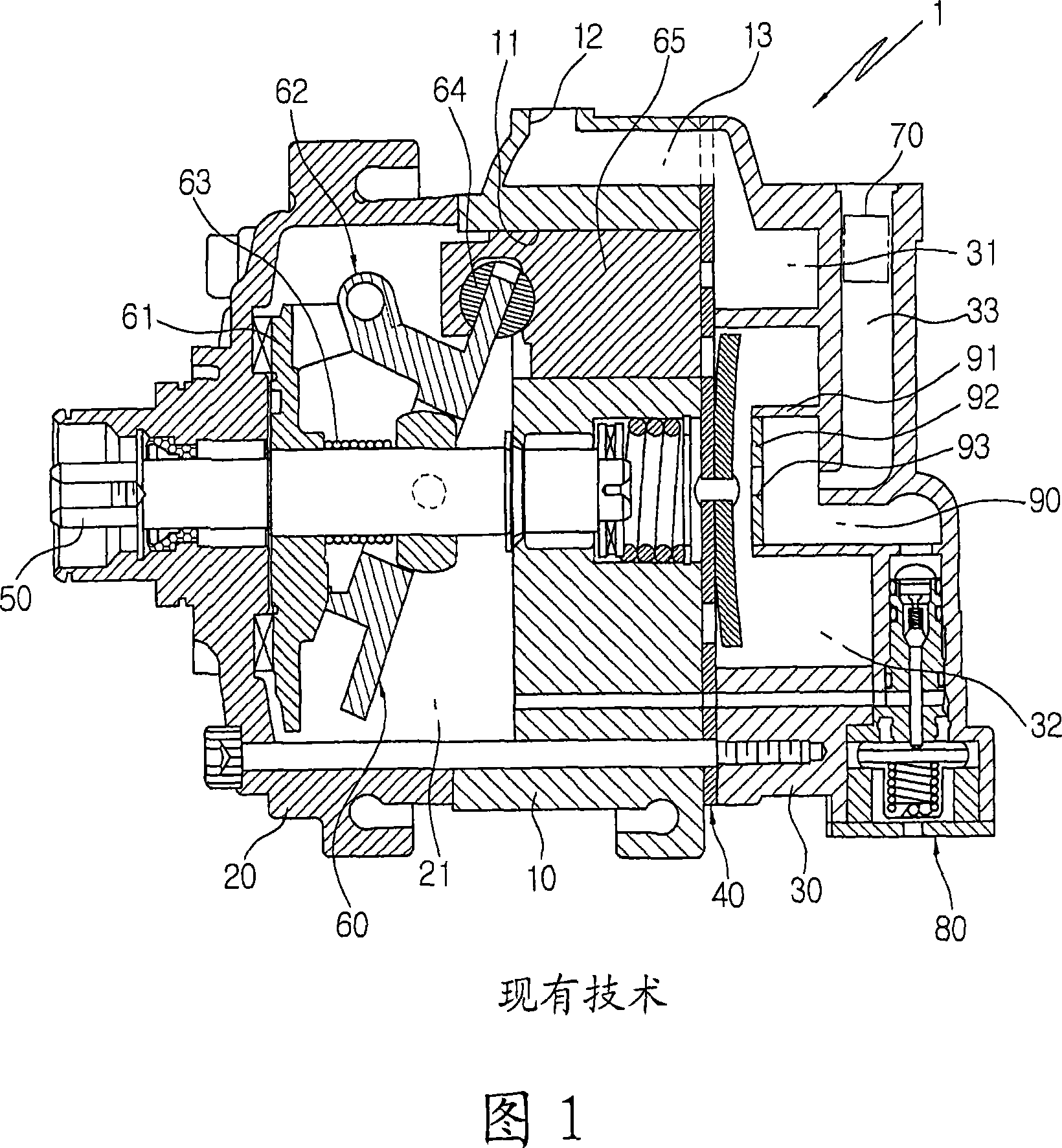
[0019] In addition, since the check valve 70 must be inserted and installed in the discharge passage 33 of the rear cover 30, an installation space for the check valve 70 must be secured, thereby increasing the size of the compressor 1

Method used


Image

  • Variable capacity swash plate type compressor
  • Variable capacity swash plate type compressor
  • Variable capacity swash plate type compressor

Examples


Embodiment Construction

[0028] Preferred embodiments of the present invention will be described in detail below with reference to the accompanying drawings.

[0029] In the present invention, descriptions of components and operations that are the same as those of the related art will be omitted.

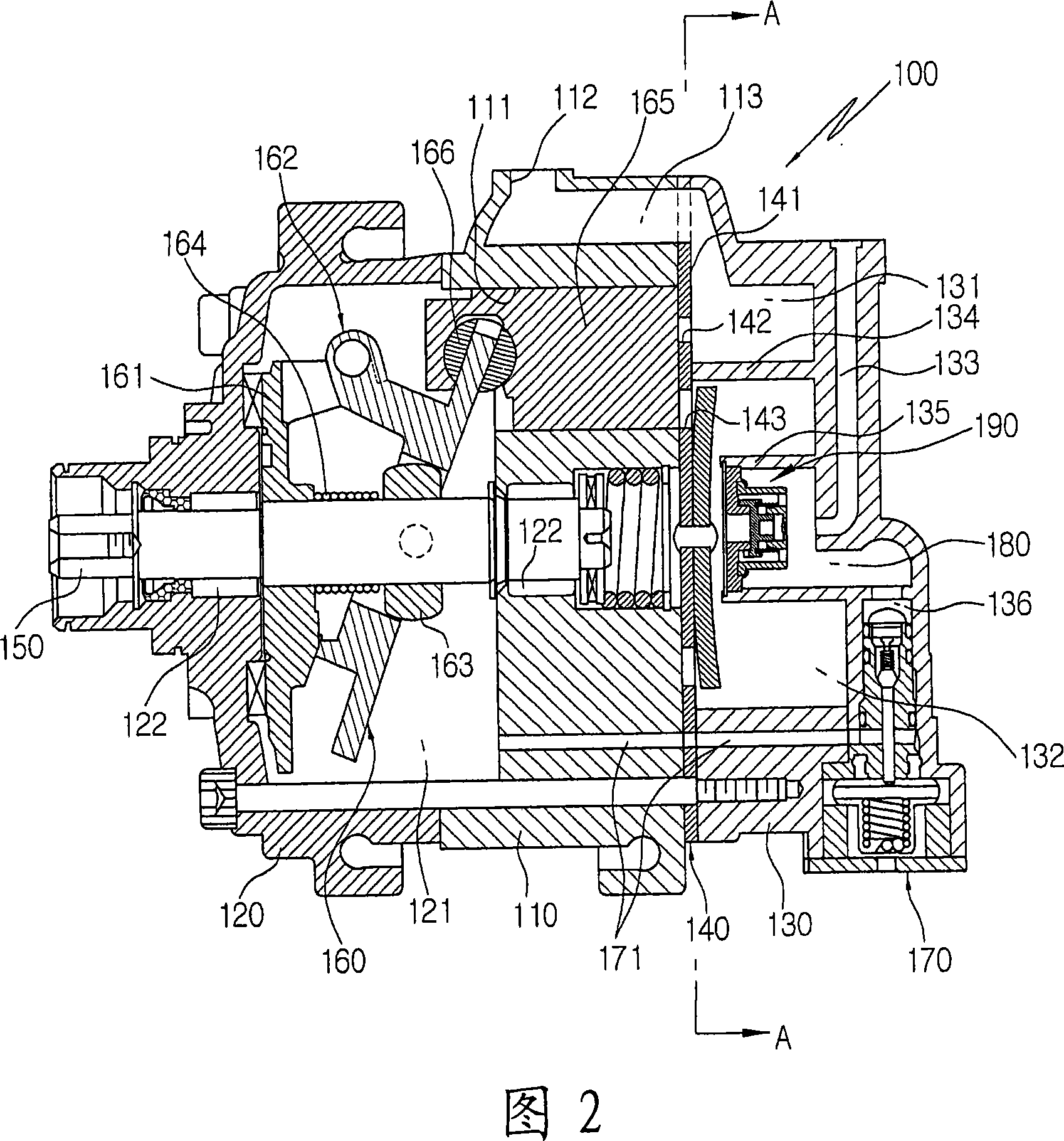
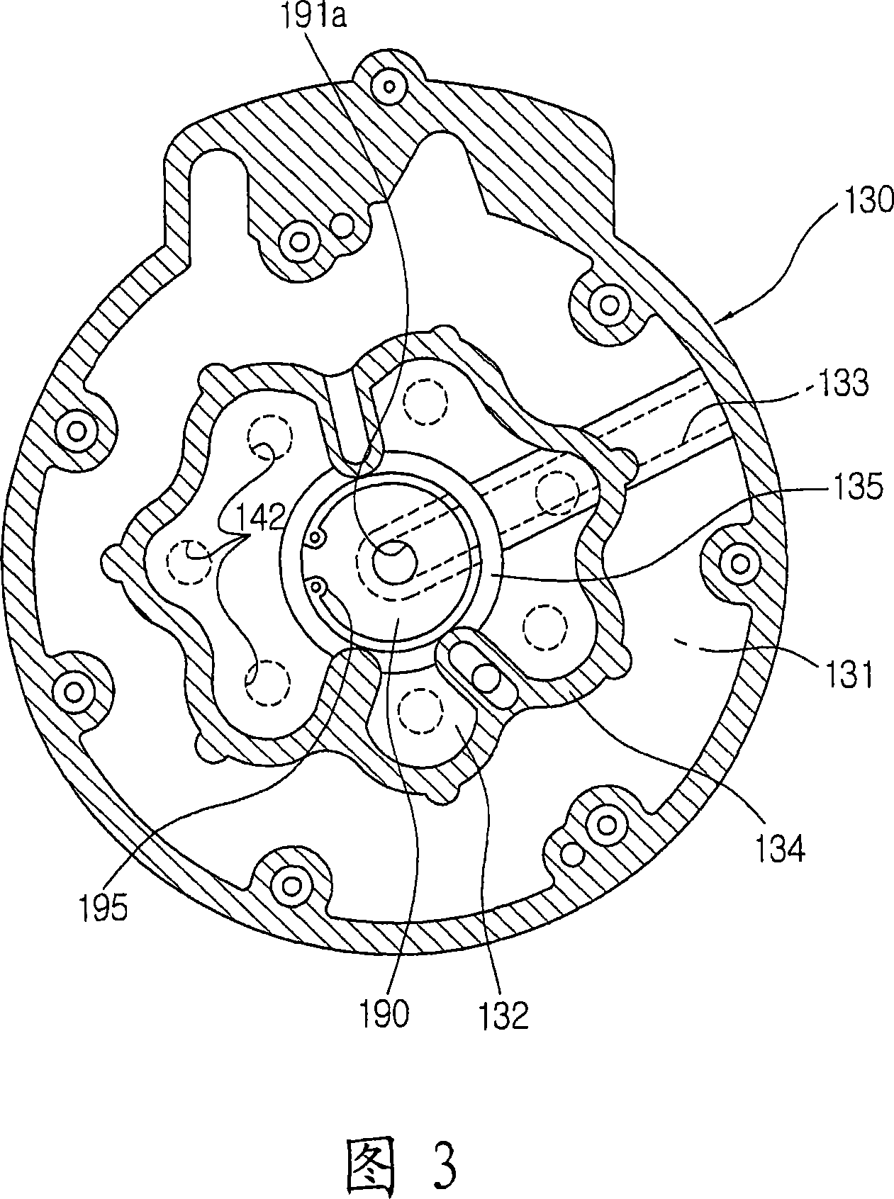
[0030] Fig. 2 is a sectional view of a swash plate type variable capacity compressor according to the present invention, Fig. 3 is a sectional view taken along line A-A of Fig. 2 , Fig. 4 is a partially enlarged sectional view of a discharge muffler chamber of a slant plate type variable capacity compressor, And Fig. 5 is a sectional view of the check valve of the swash plate type variable capacity compressor.

[0031] As shown in the figure, the swash plate type variable displacement compressor 100 according to the present invention includes: a cylinder block 110 having a plurality of cylinder holes 111 formed therein; a front cover 120 joined to the front of the cylinder block 110 and having a sealed cra...


PUM


Abstract

The present invention relates to a variable capacity swash plate type compressor, in which a check valve for circulating refrigerant inside a compressor and preventing a backflow of the refrigerant when an air conditioner is turned off is mounted on a side of a discharge muffler chamber in a cover type so that the discharge muffler chamber is formed by the check valve, thereby reducing the number of components, the number of work processes, and a pulsating pressure (pulsating noise) of discharged refrigerant, allowing that the check valve is mounted at the center of a discharge chamber without any increase in size of the compressor, preventing an overlapping phenomenon of a pulsating pressure waveform of a high-pressure refrigerant at the time of discharge since the check valve is located at the center of the discharge chamber, and preventing a separation of the check valve by fixing the check valve in the discharge chamber via a retainer.

Description

technical field [0001] The present invention relates to a slanting plate type variable capacity compressor, and more particularly to such a slanting plate type variable capacity compressor, that is, a stopper for circulating refrigerant in the compressor and preventing the refrigerant from backflowing when the air conditioner is turned off. The return valve is installed in the form of a cover on one side of the discharge muffler chamber so that the discharge muffler chamber is formed by the check valve, thereby reducing the number of parts, the number of working procedures, and reducing the pulsating pressure of the discharged refrigerant (pulsation noise ), so that the check valve can be installed at the center of the discharge chamber without increasing the size of the compressor, thereby preventing the pulsation pressure waveform superposition phenomenon of the high-pressure refrigerant at the time of discharge due to the check valve being positioned at the center of the dis...

Claims


Application Information

Patent Timeline
Patent Type & Authority Applications(China)
IPC IPC(8): F04B27/12
CPCF04B49/225F04B27/1081F04B39/0061F04B2027/1872F04B25/04F04B27/08F04B39/10
Inventor 朴泰英安休楠尹永燮
Owner HALLA CLIMATE CONTROL
Why Eureka
Eureka Blog
Learn More