
A self-suction and self-blowing vibration damping device for wind-induced vibration of stay cables

A cable-stayed wind and vibration damping device technology, which is applied to bridge parts, bridges, buildings, etc., can solve the problems that the source of vibration has not been eliminated, the result is not ideal, and reduce the wind load of cable-stayed cables, so as to prevent wind and rain The effect of exciting vibration, reducing lift force and reducing pulsating pressure

Active Publication Date: 2016-01-20
HARBIN INST OF TECH
View PDF6 Cites 0 Cited by
  • Summary
  • Abstract
  • Description
  • Claims
  • Application Information

AI Technical Summary

Problems solved by technology

[0003] At present, the control of wind-induced vibration of stay cables is mainly realized by mechanical devices such as dampers, but the results are not ideal, because the current dampers are not designed according to the multi-mode vibration of stay cables, and the dampers cannot Reduce the wind load of the stay cable, the source of its vibration has not been eliminated

Method used


Image

  • A self-suction and self-blowing vibration damping device for wind-induced vibration of stay cables
  • A self-suction and self-blowing vibration damping device for wind-induced vibration of stay cables

Examples


Embodiment 1

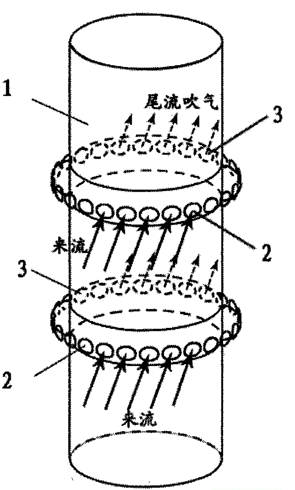
[0014] combine figure 1 , a self-suction and self-blowing vibration damping device for cable-stayed cable wind-induced vibration, comprising a plurality of circular hollow collars, the plurality of circular hollow collars are fastened on the cable-stay 1 at certain intervals, each round A plurality of air inlet holes 2 are arranged on the windward side of the shaped hollow collar, and a plurality of air outlet holes 3 are symmetrically arranged on the leeward side thereof.

Embodiment 2

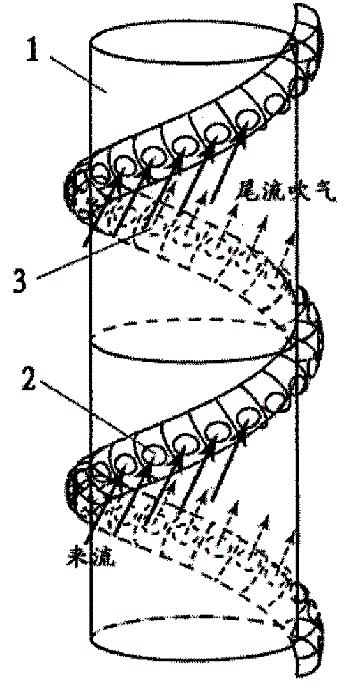
[0016] combine figure 2 , another self-suction and self-blowing vibration damping device for stay cable wind-induced vibration, comprising a spiral hollow collar, the spiral hollow collar is fastened and wound on the stay cable 1, and the spiral hollow collar There are a plurality of air intake holes 2 on the windward side, and a plurality of air outlet holes 3 on the leeward side.

Embodiment 3

[0018] The vibration reduction workflow is as follows:

[0019] (1) The airflow ejected through the air outlet of the collar breaks the alternately generated vortices in the wake and prevents the formation of wake vortices;

[0020] (2) The installation of the collar on the surface of the stay cable changes the surface form of the stay cable, which can reduce the aerodynamic force on the stay cable.

[0021] The anti-vibration protection device for the stay cables of the bridge structure of the present invention is composed of a shock-absorbing collar, an air inlet hole and an air outlet hole. The airflow ejected through the air outlet hole of the collar breaks the alternately generated vortices in the wake and prevents the formation of the wake vortex. At the same time, changing the surface form of the stay cable reduces the aerodynamic force on the stay cable surface to a certain extent. The structure is simple, and the wind-induced vibration of the bridge stay cables can b...


PUM


Abstract

The invention discloses a self-air-sucking and self-air-blowing vibration damping device for controlling wind-induced vibration of a stay cable. The self-air-sucking and self-air-blowing vibration damping device for controlling wind-induced vibration of the stay cable comprises multiple round hollow lantern rings, wherein the multiple round hollow lantern rings are fixed to the stay cable at certain intervals, multiple air inlets are formed in the windward side of each round hollow lantern ring, and multiple air outlets are formed in the leeward side of each round hollow lantern ring. Or the self-air-sucking and self-air-blowing vibration damping device for controlling wind-induced vibration of the stay cable comprises a spiral hollow lantern ring, wherein the spiral hollow lantern ring is wound around the stay cable in a fastened mode, multiple air inlets are formed in the windward side of the spiral hollow lantern ring, and multiple air outlets are formed in the leeward side of the spiral hollow lantern ring. According to the self-air-sucking and self-air-blowing vibration damping device for controlling wind-induced vibration of the stay cable, the pulsating pressure on the surface of the stay cable is greatly reduced, and the lift force of the surface of the stay cable is greatly reduced. Due to the fact that wake flow can not form vortexes which fall alternately, the width of the wake flow is reduced to a certain degree, and the resistance of the surface of the stay cable is reduced to a certain degree. The shape of the surface of the stay cable is changed, waterlines can be prevented from being formed on the surface of the stay cable to a certain degree, and wind-induced vibration of the stay cable is prevented.

Description

technical field [0001] The invention relates to a bridge structure wind-induced vibration control technology, in particular to a self-suction and self-blowing vibration damping device for stay cable wind-induced vibration. Background technique [0002] As the span increases, so does the size of its towers. For long-span suspension bridges, the cross-sectional size of many reinforced concrete bridge towers can reach 20-30 meters, and the range of the wind-induced flow field can reach several times the cross-sectional size of the bridge tower. In the circumnavigation field, it is easy to be disturbed by the wind of the bridge tower. After the wind passes through the bridge tower, a flow field will be formed around it, and the frequency of the fluctuating wind speed around the flow field can be given by the formula f v = St·U / D, where St can take 0.15 for the square column, U is the wind speed of the incoming flow, and D is the projection of the bridge tower in the vertical d...

Claims


Application Information

Patent Timeline
Patent Type & Authority Patents(China)
IPC IPC(8): E01D19/16
Inventor 欧进萍陈文礼李惠
Owner HARBIN INST OF TECH
Learn More