Latent heat storing device

A storage device, latent heat technology, applied in the direction of heat storage equipment, indirect heat exchanger, heat exchange equipment, etc., can solve the problems of difficult to manufacture and handle, expensive and so on

Inactive Publication Date: 2007-11-21
SGL CARBON SE +1
View PDF2 Cites 20 Cited by
  • Summary
  • Abstract
  • Description
  • Claims
  • Application Information

AI Technical Summary

Problems solved by technology

It is very disadvantageous from technical and economical reasons since the large number of tubes makes the device difficult and expensive to manufacture and handle

Method used


Image

  • Latent heat storing device
  • Latent heat storing device
  • Latent heat storing device

Examples


Embodiment Construction

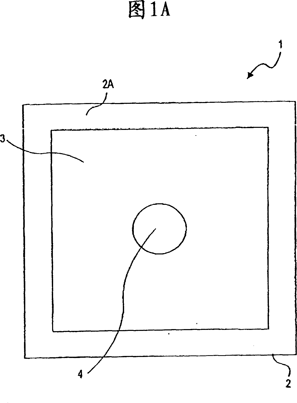
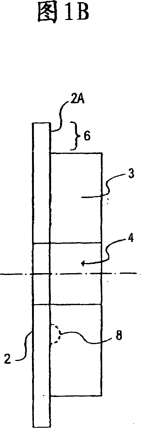
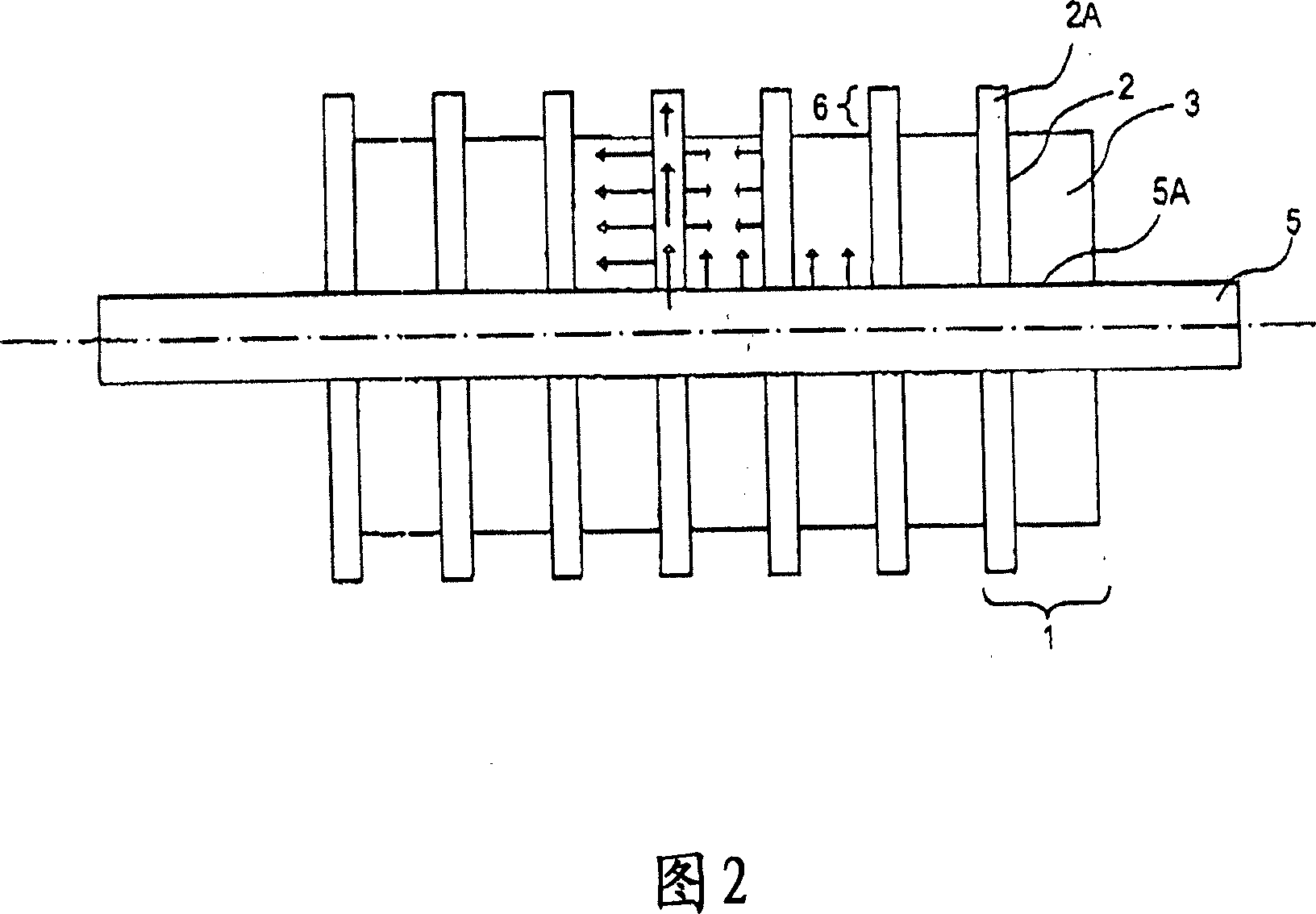
[0038] Figures 1A and 1B show, respectively, a front view and a side view of a layered composite (laminate) 1 comprising a graphite flake layer 2 and a phase change material (PCM) layer 3 in solid state. In the center of the laminate there is a through hole 4 allowing the laminate 1 to be placed on the heat exchange tubes.

[0039] In the embodiment shown in FIGS. 1A and 1B , the graphite flake layer 2 has a larger surface area than the phase change material (PCM) layer 3 in solid state. FIG. 1A shows a rectangular laminate 1 with a graphite flake layer 2 having a larger surface area than a layer 3 of phase change material. A representative size of laminate 1 is 350 x 350 x 0.5mm 3 The sheet layer 2 and 320×320×5~10mm 3 Layer 3. The difference in surface area is indicated by edge 2A. The space 6 defined by the edge 2A of the graphite flake layer 2 protruding beyond the edge of the phase change material layer 3 can be filled when the volume of the phase change material incr...


PUM

PropertyMeasurementUnit
phase transition temperatureaaaaaaaaaa
thicknessaaaaaaaaaa
thicknessaaaaaaaaaa

Abstract

A latent heat storage device including a vessel, a phase change material disposed within the vessel, at least one heat exchange interface in contact with the phase change material, at least one sheet of graphite foil which extends within the bulk of the phase change material.

Description

technical field [0001] A latent heat storage device. Background technique [0002] Phase change materials (PCMs) are capable of storing thermal energy in the form of latent heat. Such materials can undergo phase changes when heat is supplied or withdrawn, such as from solid to liquid (melting) or from liquid to solid (solidifying), or between low and high temperatures, or between hydration and dehydration, or Transitions between different liquid states. If heat is supplied or withdrawn from a phase change material, when the phase change point is reached, the temperature will remain constant until the material is completely transformed. The heat supplied or released during a phase transition that does not result in a temperature change in the material is known as latent heat. [0003] In latent heat storage devices, phase change materials can be utilized to store latent heat. The device performs injection by transferring heat (thermal energy) from the medium across the in...

Claims


Application Information

Patent Timeline
Patent Type & Authority Applications(China)
IPC IPC(8): F28D20/02C09K5/06
CPCF28F21/02Y02E60/145C09K5/063F28D20/021Y02E60/14
Inventor M·克里斯特O·奥廷格W-D·施泰因曼
Owner SGL CARBON SE
Why Eureka
Try Eureka