

Heat storage device and method of using latent heat storage material
a technology of latent heat and storage material, which is applied in the direction of indirect heat exchangers, heat storage plants, lighting and heating apparatus, etc., can solve the problem of unstable supercooled sta
- Summary
- Abstract
- Description
- Claims
- Application Information
AI Technical Summary
Benefits of technology
Problems solved by technology
Method used
Image

Examples
embodiment 1
Configuration
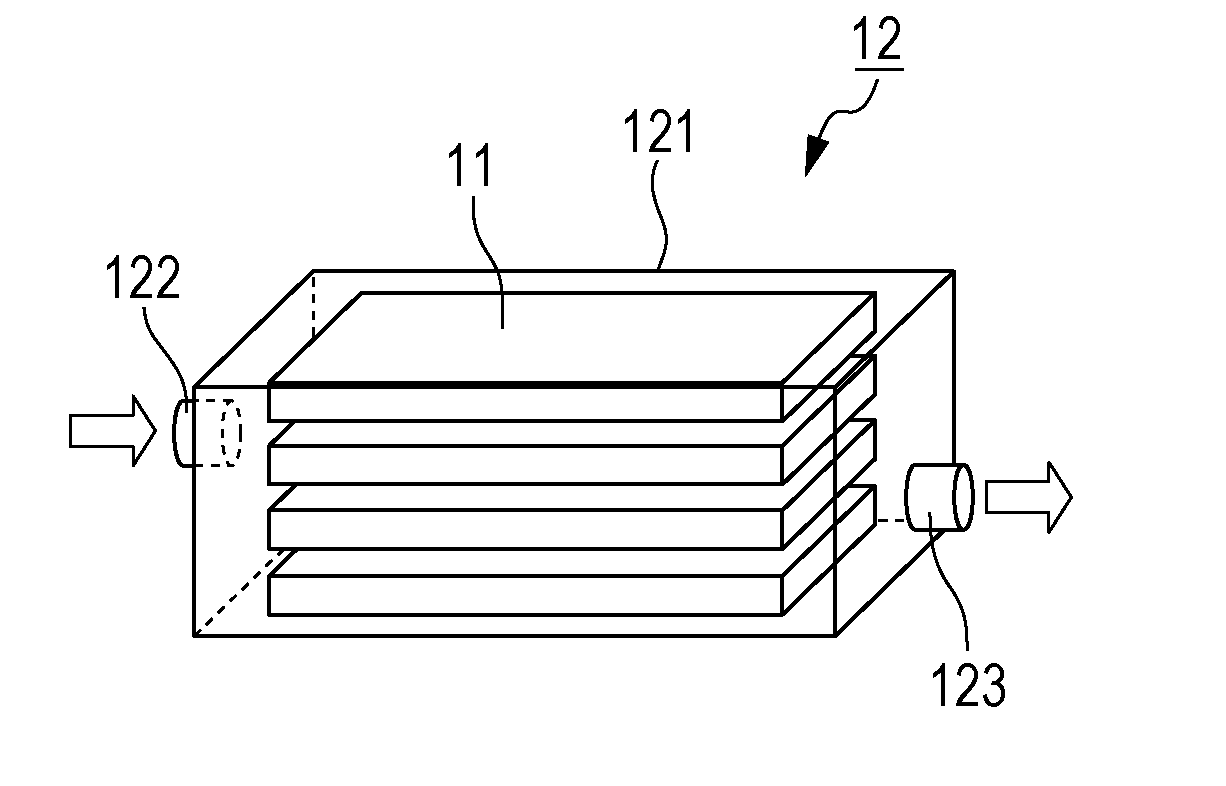
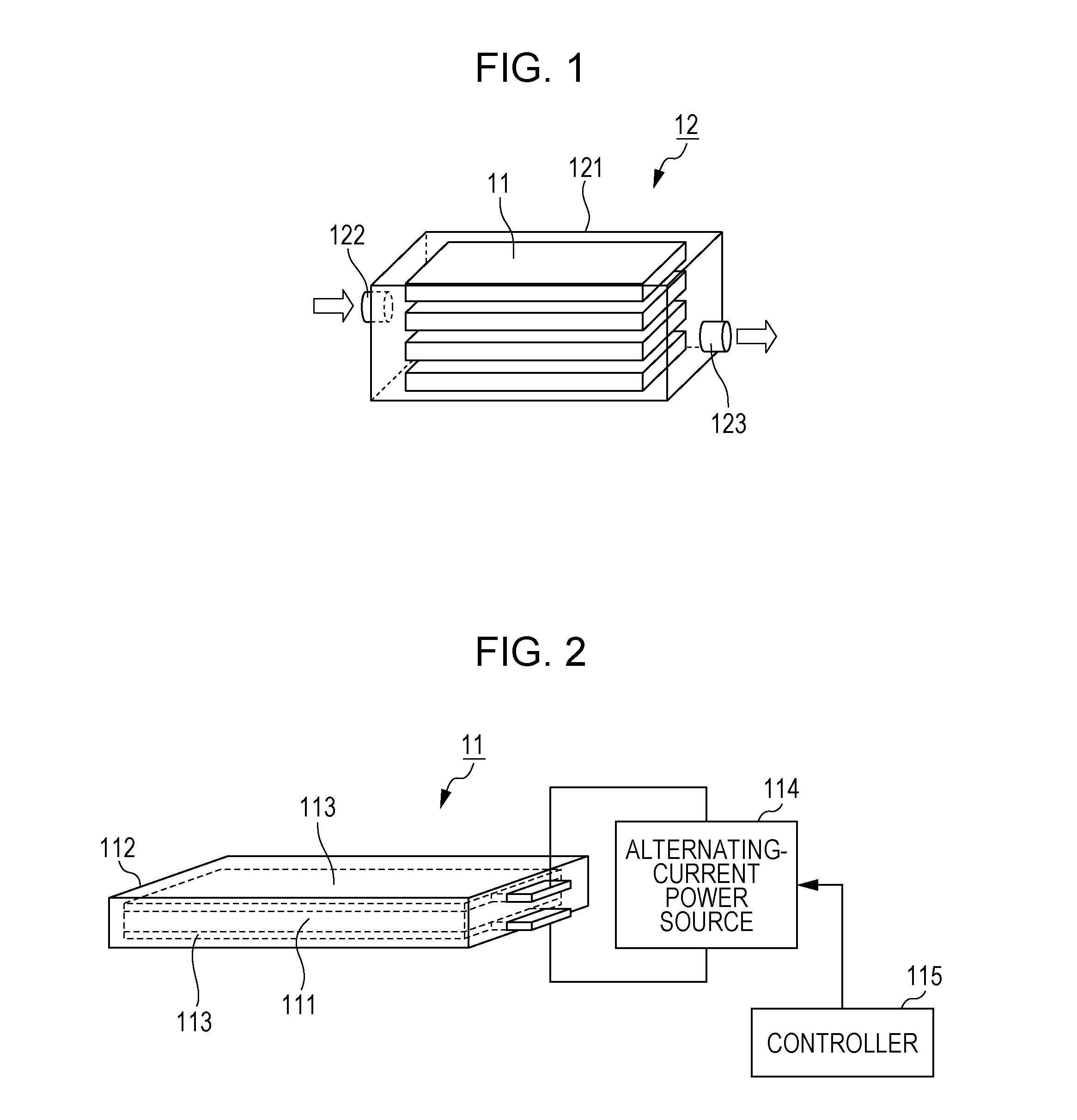
[0038]As illustrated in FIG. 1, a heat storage device 12 according to Embodiment 1 includes a plurality of heat storage units 11 and a chassis 121 in which the plurality of heat storage units 11 are contained. The plurality of heat storage units 11 are, for example, stacked at constant intervals in the chassis 121. The chassis 121 includes a heating medium inlet 122 through which a heating medium flows in and a heating medium outlet 123 through which the heating medium flows out. Heat is exchanged between the heating medium and the plurality of heat storage units 11. In the heat storage device 12, the heat exchange can be easily performed. Examples of the heating medium include water, brine, and oil.
[0039]As illustrated in FIG. 2, each of the plurality of heat storage units 11 includes a container 112 and a latent heat storage material 111 that fills the container 112. The container 112 may have a high heat conductive property. This can improve the heat conductivity of ...
experiment 1
[0066]Experiment 1 using a test unit having a similar configuration to the heat storage unit 11 of Embodiment 1 is described below.
[0067]FIG. 7 illustrates a configuration of a test unit 71 used in Experiment 1. A container 712 was an acrylic container having an inner volume of 4 mL. A latent heat storage material 711 was a sodium acetate solution having a concentration of 55% by weight. A pair of counter electrodes 713 were stainless-steel counter electrodes disposed at an interval of 2 mm. The latent heat storage material 711 filled the container 712 and was in contact with the pair of counter electrodes 713. A thermocouple 716 for detecting the temperature of the latent heat storage material 711 was inserted from a side surface of the container 712 and was in contact with the latent heat storage material 711. Twenty test units 71 having this configuration were prepared, and an alternating-current power source was connected to the counter electrodes 713 of ten test units 71 out of...
embodiment 2
[0072]In Embodiment 2, an example of a method for determining the magnitude of an alternating-current voltage applied to counter electrodes 113 is described. Configurations of heat storage units 11, a heat storage device 12, and an air heating device 13 are identical to those described in Embodiment 1. A method for driving the heat storage device 12 and the air heating device 13 is identical to that described in Embodiment 1 except for the magnitude (peak value) of the alternating-current voltage.
[Magnitude of Alternating-Current Voltage]
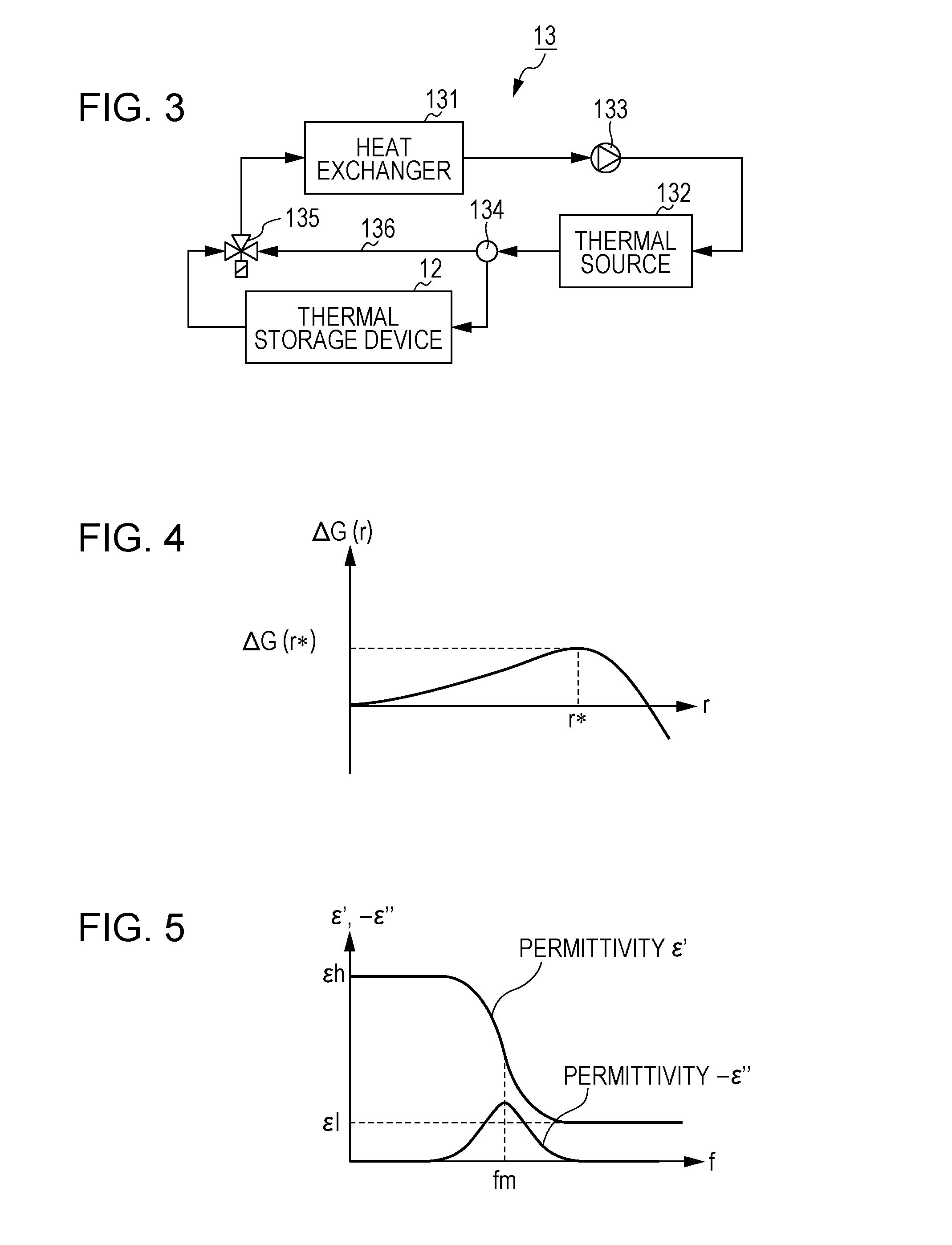
[0073]In a case where an external electric field E is being applied to a latent heat storage material 111, a free energy difference ΔG (r) may be expressed by the following expression (4):
ΔG(r)=GσΔS-GLΔTΔV+GEE2ΔVGL=ΔHρTe,GE=3ɛL(1-ɛS / ɛL)8π(2+ɛS / ɛL)(4)
[0074]where ΔS is surface area of a solid-phase particle, ΔV is a volume of the solid-phase particle, ΔT is the degree of supercooling, E is an external electric field, Gσ is a surface energy coefficient...
PUM
 Abstract
Description
Claims
Application Information