Combined high-temperature phase-transition heat storage system

A high-temperature phase change, heat storage system technology, applied in the direction of heat storage equipment, heat exchange equipment, heat exchanger types, etc., to achieve the effect of wide range of use, strong applicability, and easy amplification

Inactive Publication Date: 2011-10-19
TONGJI UNIV
View PDF10 Cites 12 Cited by
  • Summary
  • Abstract
  • Description
  • Claims
  • Application Information

AI Technical Summary

Problems solved by technology

However, at this stage, efficient large-scale heat storage systems are still rare, especially in terms of solar energy and ...

Method used


Image

  • Combined high-temperature phase-transition heat storage system
  • Combined high-temperature phase-transition heat storage system
  • Combined high-temperature phase-transition heat storage system

Examples


Embodiment 1

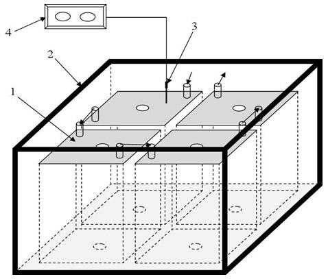
[0026] Weigh 40kg of inorganic salt phase change material lithium chloride (LiCl) with an electronic scale, load M=10kg lithium chloride (LiCl) into each high temperature phase change heat storage core 1, and then put 4 high temperature phase change heat storage cores The thermal core 1 is put into the heat preservation structure 2, and the figure 1 As shown in the heat storage system, then put the temperature measuring end of the thermocouple 3 on the ceramic protection tube and insert it into the phase change material of the high-temperature phase change heat storage core 1, and connect the other end of the thermocouple 3 to the temperature controller 4, and cover it Insulation cover. Set the upper limit temperature of the temperature controller, turn on the power supply of the heating element, and heat the device. When the temperature reaches a certain temperature above the phase change temperature of the phase change material, the heating is stopped, and the total heat st...

Embodiment 2

[0028] Take by weighing 24kg sodium carbonate (Na 2 CO 3 ) and 16kg lithium carbonate (Li 2 CO 3 ) Inorganic salt phase change material, each high temperature phase change heat storage core 1 is filled with m 1 =6kg sodium carbonate (Na 2 CO 3 ) and m 2 =4kg lithium carbonate (Li 2 CO 3 ) mixed inorganic salts evenly, and then put 4 high-temperature phase change heat storage cores 1 into the heat preservation structure 2 to form figure 1 As shown in the heat storage system, the temperature measuring end of the thermocouple 3 is covered with a ceramic protection tube and inserted into the phase change material, the other end of the thermocouple 3 is connected to the temperature controller 4, and the heat preservation cover is covered. Set the upper limit temperature of the temperature controller, turn on the power supply of the heating element, and heat the material. When the temperature reaches a certain temperature above the phase change temperature of the phase chan...

Embodiment 3

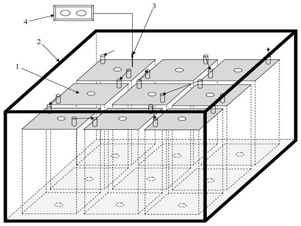
[0030] Take by weighing 54kg sodium carbonate (Na 2 CO 3 ) and 36kg lithium carbonate (Li2 CO 3 ) Inorganic salt phase change material, each high temperature phase change heat storage core 1 is filled with m 1 =6kg sodium carbonate (Na 2 CO 3 ) and m 2 =4kg lithium carbonate (Li 2 CO 3 ) mixed inorganic salts evenly, and then put 9 high-temperature phase change heat storage cores 1 into the heat preservation structure 2 to form figure 2 As shown in the heat storage system, the temperature measuring end of the thermocouple 3 is covered with a ceramic protection tube and inserted into the phase change material, the other end of the thermocouple 3 is connected to the temperature controller 4, and the heat preservation cover is covered. Set the upper limit temperature of the temperature controller, turn on the power supply of the heating element, and heat the phase change heat storage core. When the temperature reaches a certain temperature above the phase change temperat...


PUM


Abstract

The invention belongs to the technical field of a high-temperature phase-transition heat storage material, and particularly relates to a combined high-temperature phase-transition heat storage system. The combined high-temperature phase-transition heat storage system is formed by combining a plurality of high-temperature phase-transition heat storage core devices in a certain way; and by adopting the combined and modularized application, the aim of large heat storage and high heat storage efficiency is achieved. The high-temperature phase-transition heat storage cores can be designed to be different structural forms; subsequently according to different heat storage requirements, the high-temperature phase-transition heat storage cores are combined for use in a certain way so as to achieve the aim of storing a certain quantity of heat; the same heat source can be used for heat storage; and a thermal insulation structure is arranged outside the whole heat storage system so as to reduce heat dissipation. During the running process, the whole heat storage system can be controlled by controlling one high-temperature phase-transition heat storage core; the combined high-temperature phase-transition heat storage system can be operated simply and can be used conveniently; furthermore, the heat storage quantity of the whole system is adjustable; the heat storage efficiency is high; the applicable scope is wide, the equipment investment is less, the maintenance is convenient and the adaptability is strong.

Description

technical field [0001] The invention belongs to the technical field of high-temperature phase-change heat storage, and in particular relates to a combined high-temperature phase-change heat storage system. Background technique [0002] Since the world energy crisis in the 1970s, the basic application research of heat storage technology has risen rapidly and continued to develop in developed countries, and now it has become an important part of developing new energy, solving the mismatch between energy supply and demand in terms of time and intensity, and improving energy utilization efficiency. One of the techniques. As a heat storage material, phase change materials can store excess energy and release it according to different needs, so that energy can be used reasonably. Phase change heat storage technology has been applied in solar thermal power generation, industrial heat utilization and waste heat recovery, power peak shaving, building energy conservation, agricultural...

Claims


Application Information

Patent Timeline
IPC IPC(8): F28D20/02F28F27/00
CPCY02E60/14
Inventor 张东李明广李月锋张洋
Owner TONGJI UNIV
Why Eureka
Try Eureka