

Method and apparatus for high-voltage Hall effect
A technology of Hall effect and measuring device, which is applied in the direction of measuring device, measuring magnetic variable, magnetic performance measurement, etc., can solve the problems such as the inability to realize Hall effect measurement of anvil
- Summary
- Abstract
- Description
- Claims
- Application Information
AI Technical Summary
Problems solved by technology
Method used
Image

Examples
Embodiment 1
[0028] Embodiment 1 illustrates the structure of the device of the present invention in conjunction with the accompanying drawings
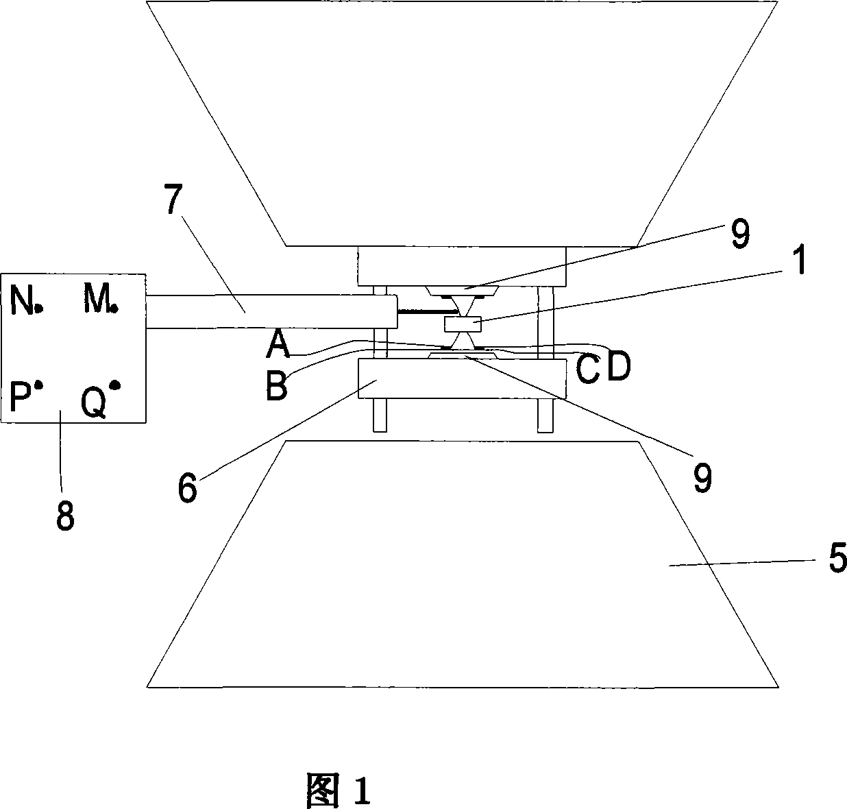
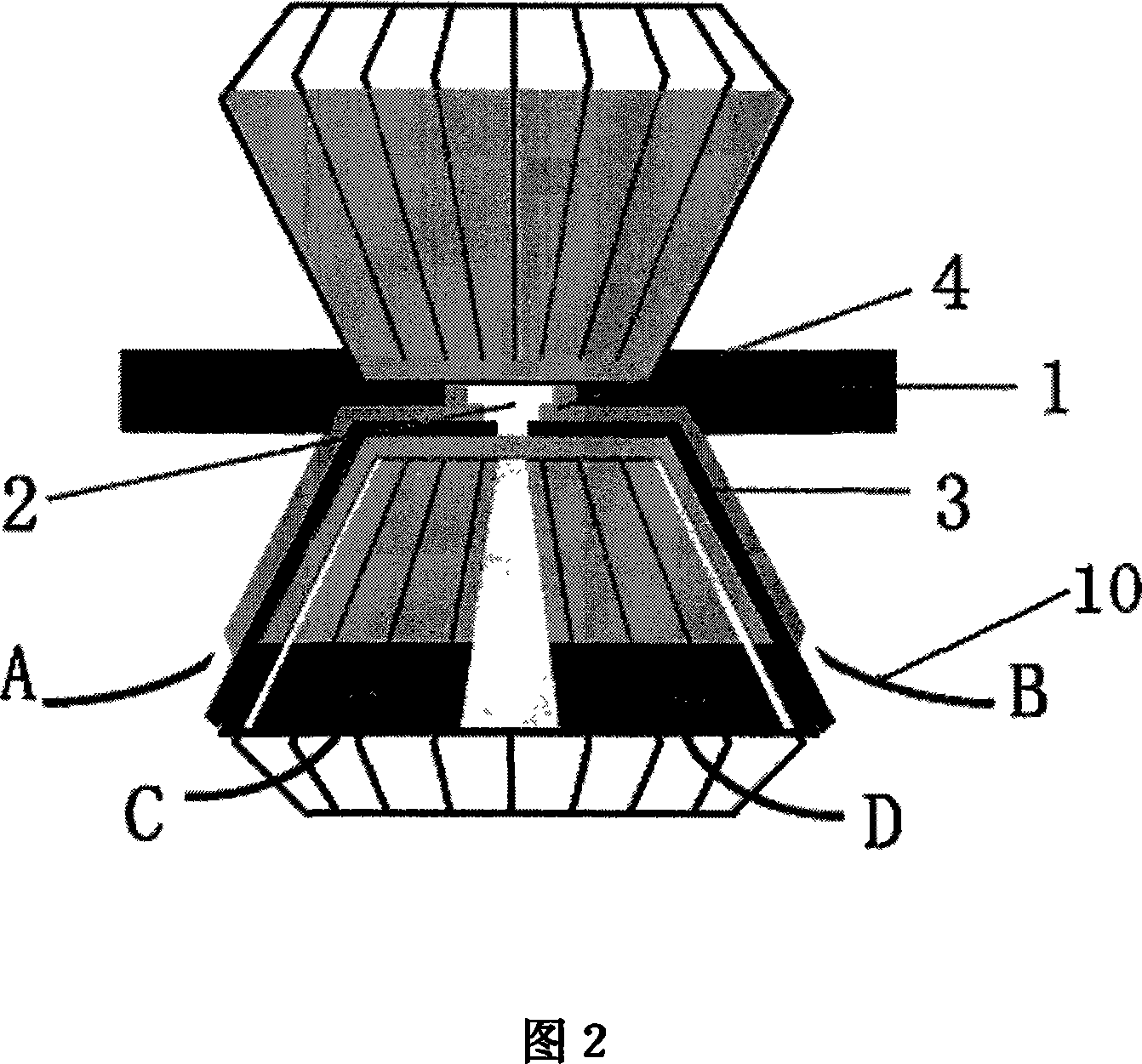
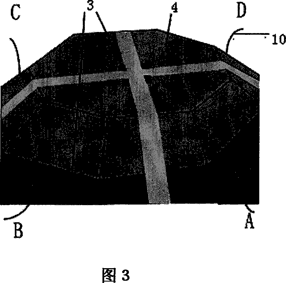
[0029]1 to 3 show the structure of the device of the present invention. Among them, 1 is a spacer, placed between two diamond anvils, which can be made of metal rhenium with a purity of more than 99.9%; 2 is a sample cavity, which is surrounded by two diamond anvils and spacer 1 to place samples 3 is an electrode, which is deposited on a diamond anvil surface and four mutually insulated electrodes on the side, which can be made of platinum material; 4 is a protective layer, which is deposited on the diamond anvil surface and the side surface of the covering electrode 3 Aluminum oxide layer, however, has the terminal end of electrode 3 to expose respectively on diamond anvil anvil surface and side; The exposed ends of the electrodes 3 are electrically connected to the four connection points M, N, P and Q of the Hall automatic test system 8 respec...
Embodiment 2
[0030] Embodiment 2 illustrates the uniformity of the magnetic field,
[0031] Because the diameter of the shaking table 9 is 22mm, the middle is a small hole with a diameter of 1mm, the whole shaking table 9 is not an entity, therefore, the magnetic field generated between the two shaking tables 9 is not completely uniform, as shown in Fig. 4 Magnetic field distribution between out shaker 9. Because the present invention uses non-magnetic press 6 and spacer 1, uses the shaker 9 that contains ferromagnetic material, produces an almost uniform magnetic field region in the center of the shaker 9 with a diameter of 10mm. Fig. 5 provides the error comparison between the magnetic field strength at the position of the sample (sample cavity 3) and the magnetic field strength detected at the position of the gauss meter probe 7, and the calculation formula is: the measured value of the gauss meter probe-the magnetic field strength value at the position of the sample [that is The value...
Embodiment 3
[0033] Embodiment 3 test process and measurement result
[0034] The measuring method of the present invention adopts the van der Pauw method to measure, taking the HgTe sample as an example, the specific experimental steps are as follows:
[0035] Assemble the device into the form shown in Figure 1.
[0036] The test process is to place the gauss meter probe 7 on the gasket 1, and the top of the gauss meter probe 7 touches the side of the diamond anvil; apply current to the electromagnet 5, rotate the gauss meter probe 7 to detect the magnetic field strength, and when the gauss meter shows the maximum Fix the Gauss meter probe 7 at the same time; then connect the 4 electrodes 3 on the diamond anvil to the 4 connection points on the Hall automatic test system 8 according to the right-hand rule; turn on the Hall automatic test system 8 for data measurement .
[0037] During the test, if the direction of the magnetic field does not pass through the sample vertically, the gauss...
PUM
| Property | Measurement | Unit |
|---|---|---|
| Thickness | aaaaa | aaaaa |
Abstract
Description
Claims
Application Information