
Non-linear magnetic field sensors and current sensors

A technology of magnetic sensors and sensor equipment, applied in the field of nonlinear sensors and sensors, which can solve problems such as poor SNR

Active Publication Date: 2007-11-21
KONINKLIJKE PHILIPS ELECTRONICS NV
View PDF2 Cites 18 Cited by
  • Summary
  • Abstract
  • Description
  • Claims
  • Application Information

AI Technical Summary

Problems solved by technology

However, in recent decades, this method has often yielded poor SNR

Method used


Image

  • Non-linear magnetic field sensors and current sensors
  • Non-linear magnetic field sensors and current sensors
  • Non-linear magnetic field sensors and current sensors

Examples


Embodiment Construction

[0043] The present invention will be described below with respect to specific embodiments and with reference to the accompanying drawings, but the present invention is not limited thereto but is defined by the claims. Any reference signs in each claim should not be construed as limiting its scope. The drawings described are only schematic and not limiting. In the drawings, the size of some of the elements is exaggerated and not drawn on scale for illustrative purposes. The term "comprising" used in the present description and claims does not exclude other elements or steps. Whereas when referring to a singular noun, the use of an indefinite or definite article eg "a" includes a plurality of such nouns unless something else is specifically stated.

[0044] In addition, in the description and claims, the terms first, second, third, etc. are used to distinguish between the same element and not necessarily to describe a sequential or chronological order. It is to be understood ...


PUM


Abstract

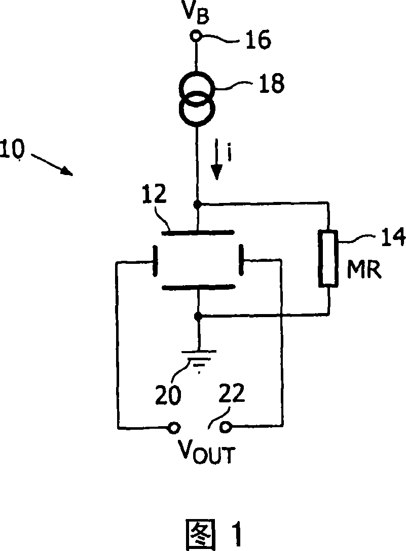
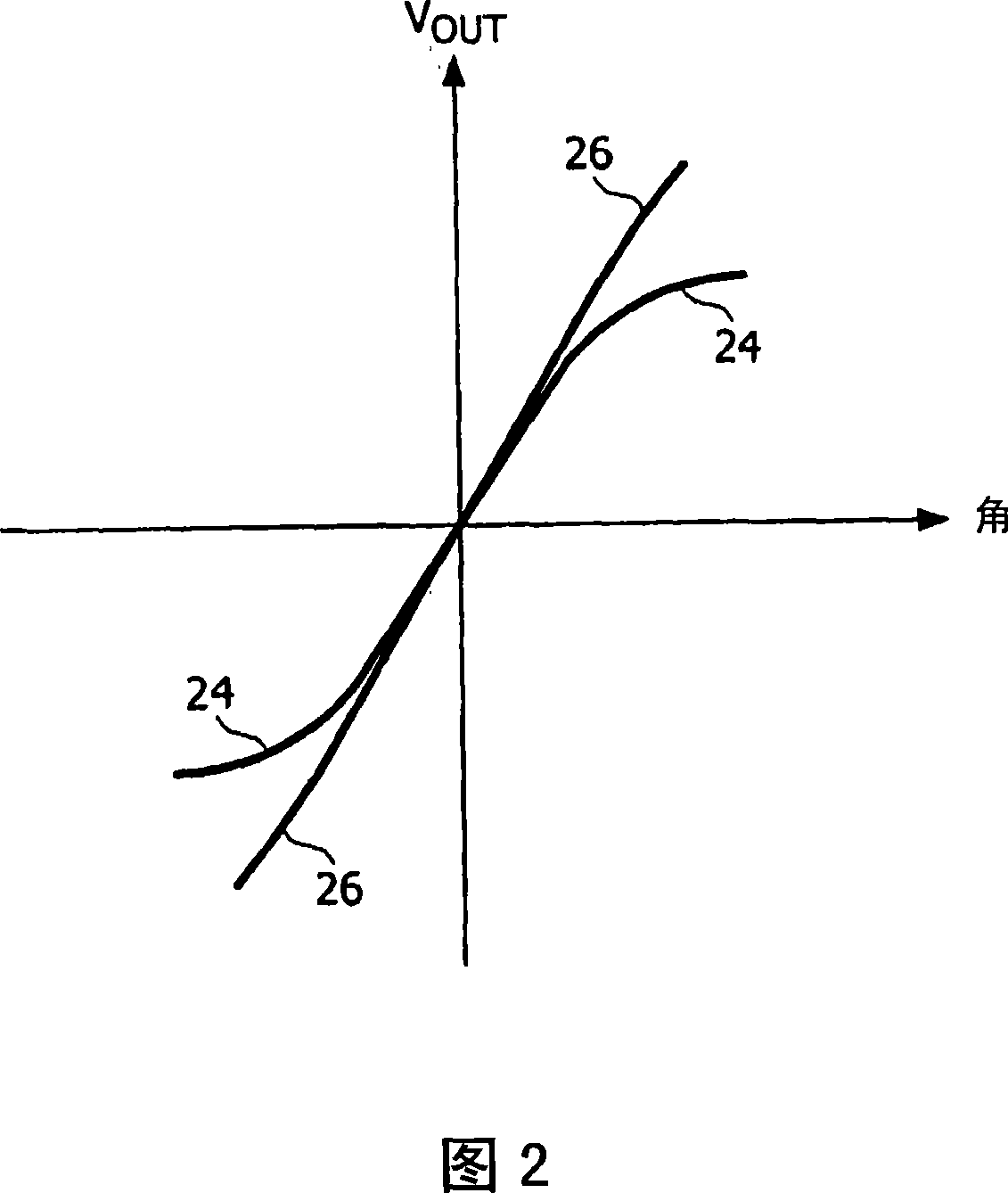
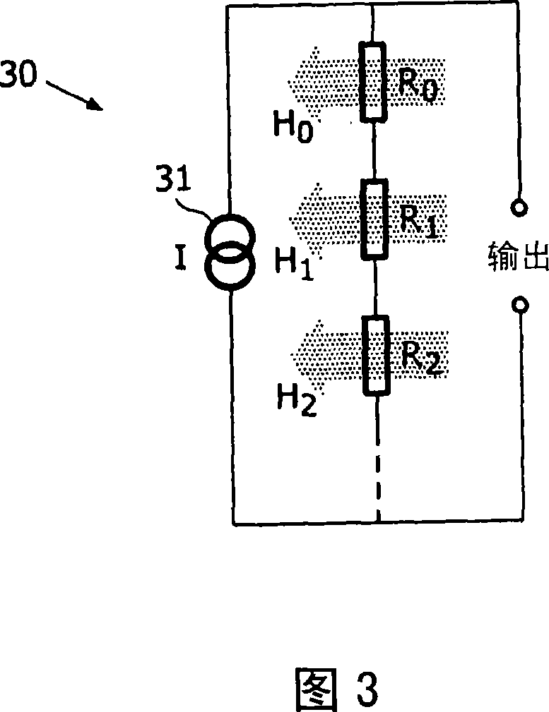
The invention provides a magnetic field sensor or current sensor which can exhibit a substantially linear relationship between the sensor signal and the logarithm of the magnetic field or current. The sensor may be used as a wide dynamic range sensor which can offer a constant relative sensitivity and a uniform SNR over several decades. The design of the sensor device may be implemented in discrete magnetic field sensors or current sensors as well as in integrated current sensors in ICs comprising MRAM modules.

Description

technical field [0001] The present invention relates to sensors, and in particular to nonlinear sensors, such as those that exhibit a substantially linear relationship between the sensor signal and the logarithm of the property measured by the sensor, and can be used as Wide dynamic range sensor that provides constant relative sensitivity and uniform SNR. Background technique [0002] By definition, a magnetoresistive (MR) sensor is a linear sensor in the range of measurement. The most widely used MR sensor types in the medium and low field range are based on the anisotropic magnetoresistance (AMR) effect, the giant magnetoresistance (GMR) effect or, more recently, the tunneling magnetoresistance (TMR) effect. [0003] In principle, a "good" magnetic sensor is one that exhibits linear properties over the field detection range, beyond which the sensor signal saturates. Thus, the sensitivity of the sensor, which is determined by the slope of the linear part of the characteri...

Claims


Application Information

Patent Timeline
Patent Type & Authority Applications(China)
IPC IPC(8): G01R33/06G01R33/09G01R33/07G01R15/20
CPCB82Y25/00G01R15/20G01R15/202G01R15/205G01R15/207G01R33/06G01R33/07G01R33/09G01R33/093
Inventor 金·潘勒亚普·鲁伊戈罗克
Owner KONINKLIJKE PHILIPS ELECTRONICS NV
Learn More