

Piezoresistive Micromechanical Sensor Component and Corresponding Measuring Method
a micromechanical sensor and micro-mechanical technology, applied in the direction of measuring devices, speed/acceleration/shock measurement, instruments, etc., can solve the problems of increasing process outlay with respect to the required trenches and reducing mechanical sensitivity
- Summary
- Abstract
- Description
- Claims
- Application Information
AI Technical Summary
Benefits of technology
Problems solved by technology
Method used
Image

Examples
first embodiment
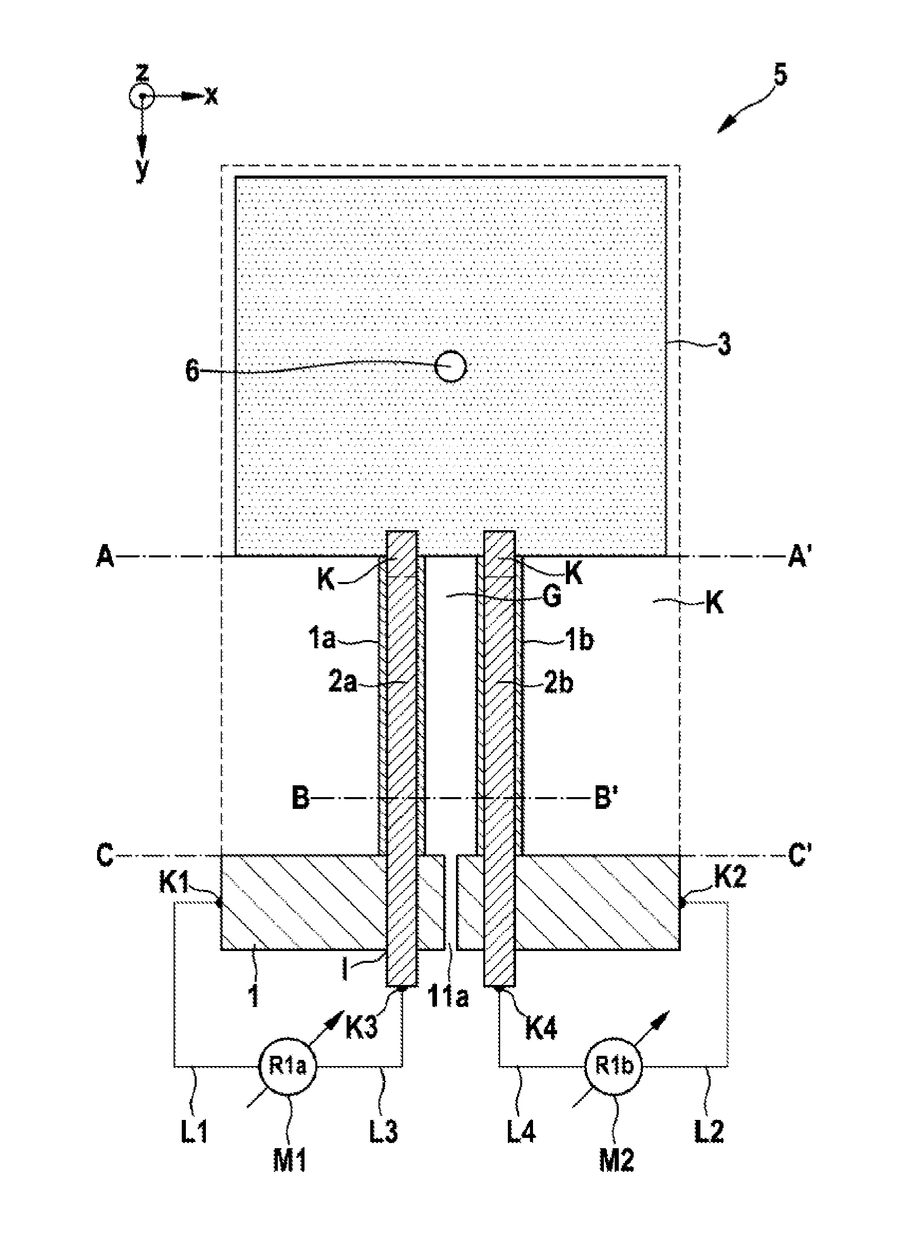
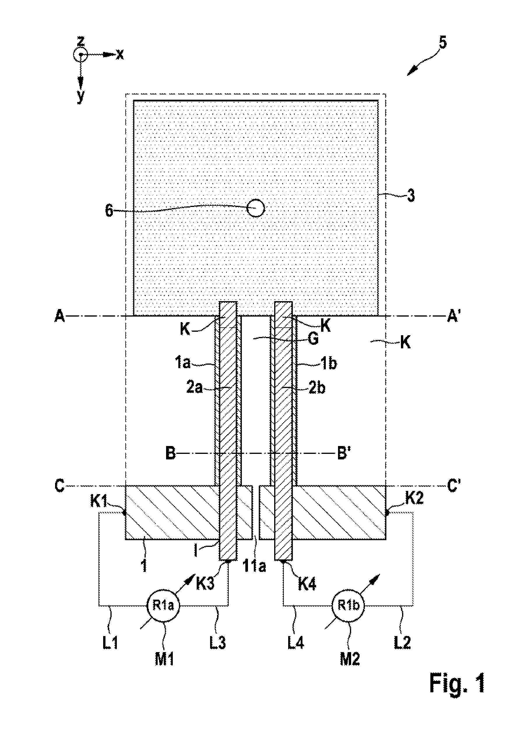
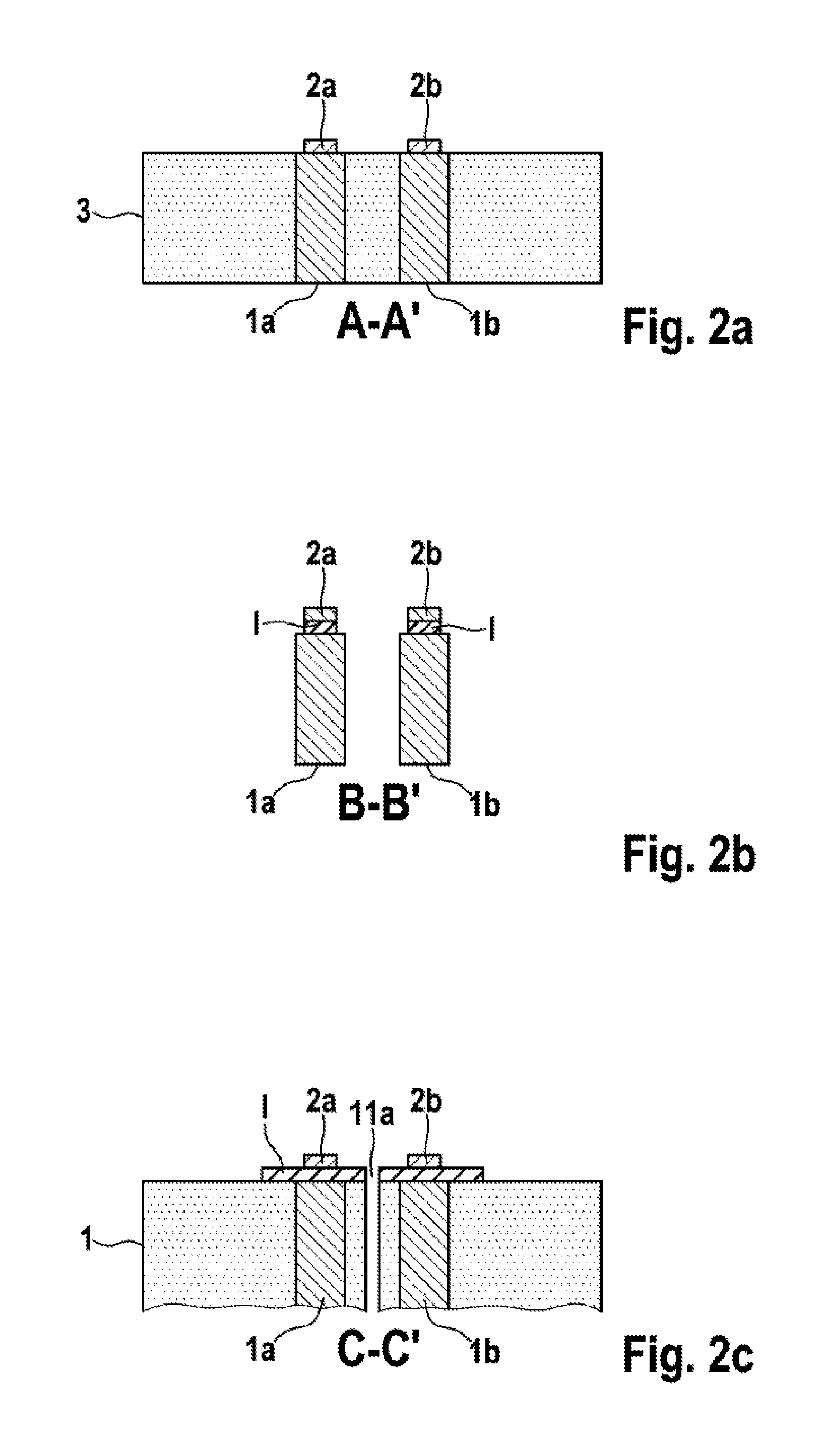
[0026]FIG. 1 is a plan view of a piezoresistive micromechanical sensor component in the form of a micromechanical acceleration sensor arrangement according to the present invention, and FIGS. 2a-c illustrate cross sections of the piezoresistive micromechanical sensor component in the form of a micromechanical acceleration sensor arrangement according to FIG. 1 along the lines AA′, BB′ and CC′.
[0027]In FIG. 1, reference 5 denotes a piezoresistive micromechanical acceleration sensor. Starting from the substrate 1, two homogeneously doped piezoresistive beams 1a, 1b extend to the seismic mass 3, which is therefore connected to the substrate 1 via these beams 1a, 1b. Below the beams 1a, 1a and the seismic mass 3, there is a cavity K.
[0028]The insulation trench G between the piezoresistive beams 1a, 1b may also be configured as a narrow insulation trench (STI). In this way, the beams 1a, 1b can be placed closer to the rotation point, the effect of which is to amplify the lever action.
[00...
second embodiment
[0036]FIG. 3 is a plan view of a piezoresistive micromechanical sensor component in the form of a micromechanical acceleration sensor arrangement 5′ according to the present invention.
[0037]In the second embodiment, shown in FIG. 3, an undoped bending beam 7 is provided which connects the seismic mass 3 to the substrate 1. Here, the homogeneously doped piezoresistive beams 1a′, 1b′ are provided not between the substrate 1 and the seismic mass 3 but between the substrate 1 and this bending beam 7. Such a configuration, the piezoresistive beams 1a′, 1b′ being placed at an angle α (here: 90°) with respect to the bending beam 7, allows greater geometrical freedom, for example a modified length of the beams 1a, 1b with a constant distance between the centre of gravity 6 of the seismic mass 3 and the point of suspension from the substrate 1 (lever arm length).
[0038]The angle α is of course not restricted to 90°, but may be varied freely. Also, the beams 1a′, 1b′ do not need to have the sa...
PUM
 Abstract
Description
Claims
Application Information