Semiconductor device and production method therefor
a technology of semiconductor and production method, which is applied in the direction of semiconductor/solid-state device manufacturing, solid-state devices, electric devices, etc., can solve the problems of deterioration in area efficiency in integrated circuits, significant restriction of flexibility in laying lines in first layers, and difficulty in fully taking advantage of the area reduction effect of sgt, etc., to facilitate a reduction of element isolation width, enhance area efficiency, and reduce an element's area efficiency
- Summary
- Abstract
- Description
- Claims
- Application Information
AI Technical Summary
Benefits of technology
Problems solved by technology
Method used
Image
Examples
first embodiment
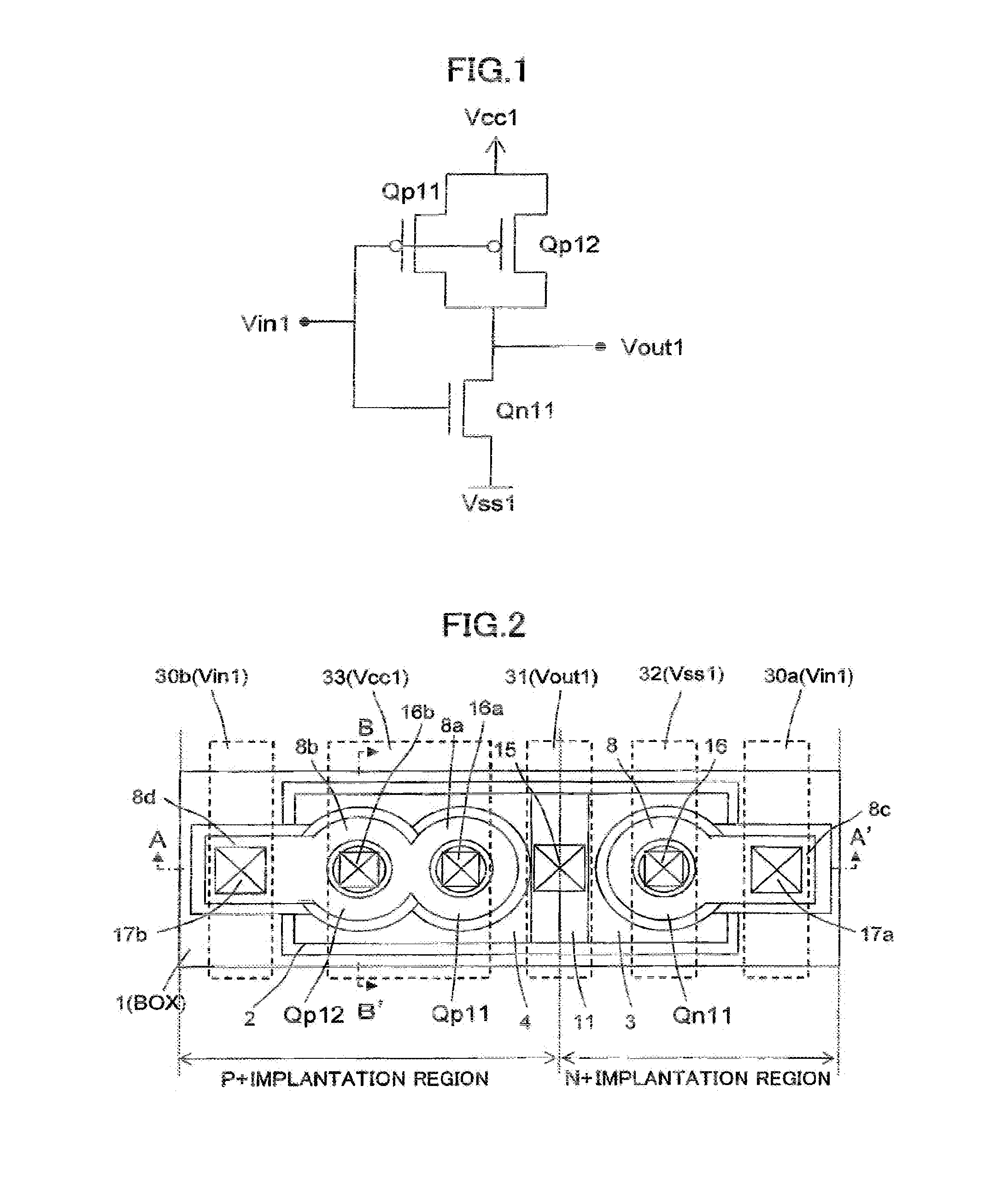
[0187]FIG. 1 is an equivalent circuit diagram of a CMOS inverter according to a first embodiment of the present invention. A circuit operation of the CMOS inverter will be described below. An input signal Vin 1 is applied to a gate of an NMOS Qn 11 and respective gates of two PMOSs Qp 11, Qp 12. When the Vin 1 is “1”, the NMOS Qn 11 is placed in an ON state, and each of the PMOSs Qp 11, Qp 12 is placed in an OFF state, so that an output signal Vout 1 becomes “0”. Reversely, when the Vin 1 is “0”, the NMOS Qn 11 is placed in an OFF state, and each of the PMOSs Qp 11, Qp 12 is placed in an ON state, so that the Vout 1 becomes “1”. As above, the CMOS inverter is operable to allow the output signal Vout 1 to have a value opposite to that of the input signal Vin 1.
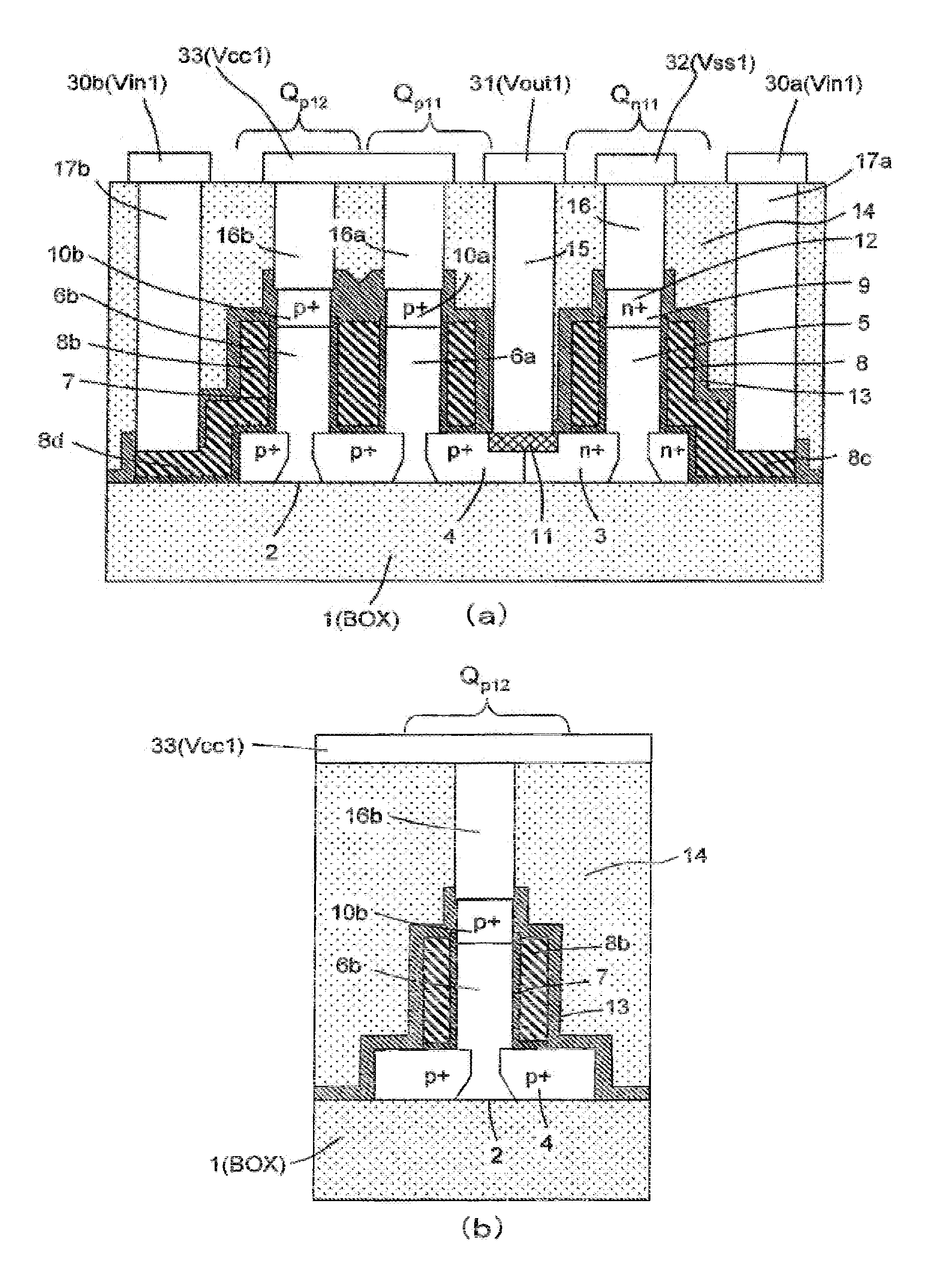
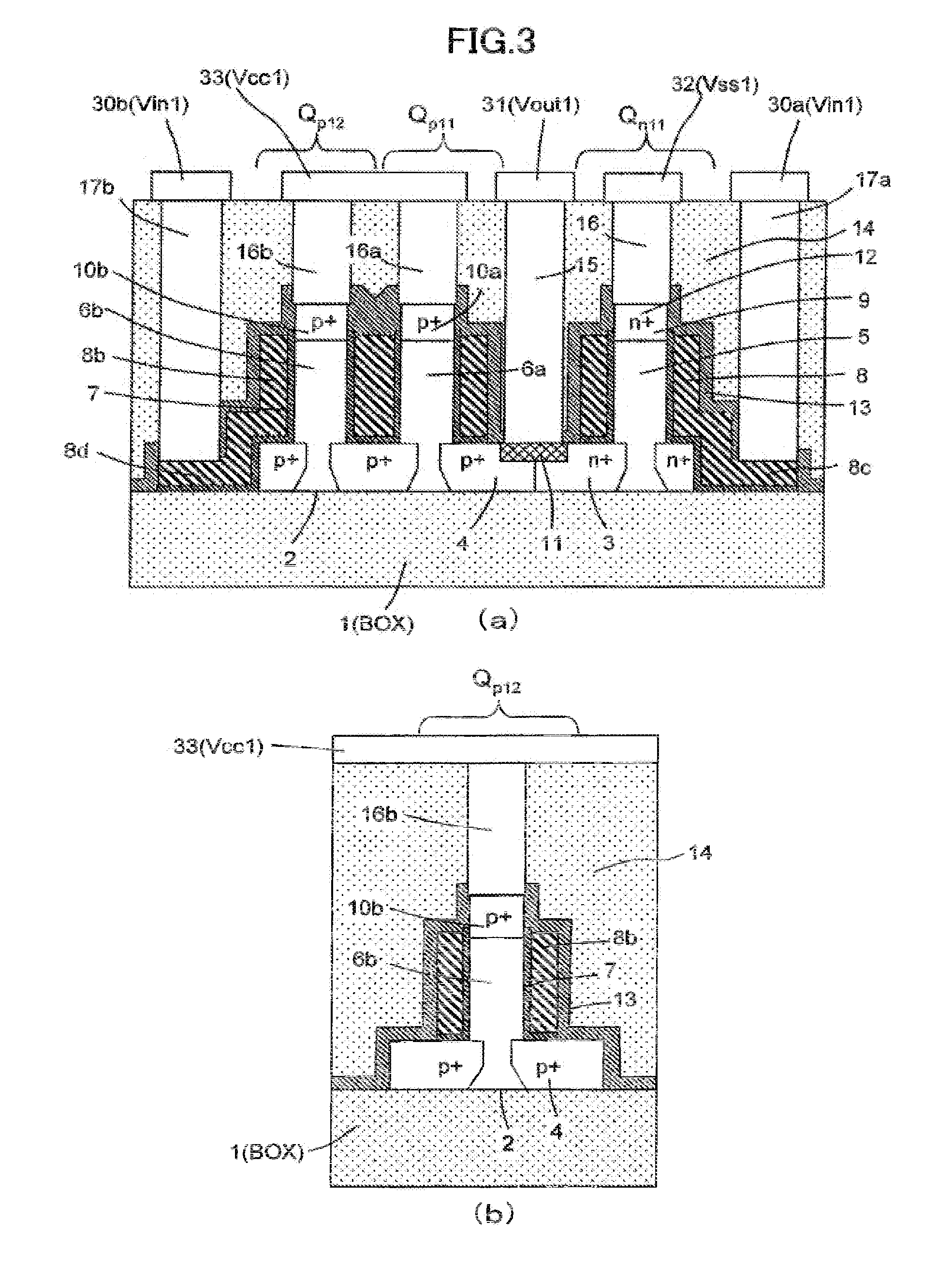
[0188]FIG. 2 is a top plan view of the CMOS inverter according to the first embodiment. FIGS. 3(a) and 3(b) are sectional views taken along the cutting-plane line A-A′ and the cutting-plane line B-B′ in FIG. 2, respectively. Wi...
second embodiment
[0235]A second embodiment of the present invention shows one example of a CMOS inverter made up using an SGT with a structure where a silicide layer is formed over the entire surface of drain diffusion layers formed in a planar silicon layer, and on a source diffusion layer formed in an upper portion of a pillar-shaped silicon layer. As a result of forming a silicide layer over the entire surface of the drain diffusion layers formed in the planar silicon layer, a parasitic resistance of the drain diffusion layers can be reduced. In addition, as a result of forming a silicide layer on the source diffusion layer formed in the upper portion of the pillar-shaped silicon layer, a parasitic resistance of the source diffusion layer can be reduced. The silicide layers to be formed on the drain diffusion layer and the source diffusion layer can be formed only on the drain diffusion layer and the source diffusion layer through a single process in a self-alignment manner.
[0236]FIG. 32 is an eq...
third embodiment
[0255]A third embodiment of the present invention shows one example of an SGT having a structure where a single contact is formed on tops of two or more pillar-shaped silicon layers in such a manner as to be shared by the pillar-shaped silicon layers.
[0256]FIG. 43 is an equivalent circuit diagram of a CMOS inverter according to the third embodiment. A circuit operation of the CMOS inverter is the same as that in the second embodiment, and its description will be omitted here.
[0257]FIG. 44 is a top plan view of the CMOS inverter according to the third embodiment. FIGS. 45(a) and 45(b) are sectional views taken along the cutting-plane line A-A′ and the cutting-plane line B-B′ in FIG. 44, respectively.
[0258]The third embodiment is different from the second embodiment in that, in the third embodiment, source diffusion layers formed in respective upper portions of adjacent two pillar-shaped silicon layers 306a, 306b forming PMOSs Qp 41, Qp 42, are connected to each other through a rectan...
PUM
 Abstract
Description
Claims
Application Information
 - R&D
- Intellectual Property
- Life Sciences
- Materials
- Tech Scout
- Unparalleled Data Quality
- Higher Quality Content
- 60% Fewer Hallucinations
Browse by: Latest US Patents, China's latest patents, Technical Efficacy Thesaurus, Application Domain, Technology Topic, Popular Technical Reports.
© 2025 PatSnap. All rights reserved.Legal|Privacy policy|Modern Slavery Act Transparency Statement|Sitemap|About US| Contact US: help@patsnap.com


