Device for sealing timepiece crown wheel

A technology of sealing device and crown, applied in the field of watches and clocks, can solve problems such as troublesome operation

Inactive Publication Date: 2010-09-22
拉斐尔科恩
View PDF10 Cites 0 Cited by
  • Summary
  • Abstract
  • Description
  • Claims
  • Application Information

AI Technical Summary

Problems solved by technology

However, the small size of the cap and the small clamps are cumbersome to operate and don't put enough pressure on the crown

Method used


Image

  • Device for sealing timepiece crown wheel
  • Device for sealing timepiece crown wheel
  • Device for sealing timepiece crown wheel

Examples


Embodiment Construction

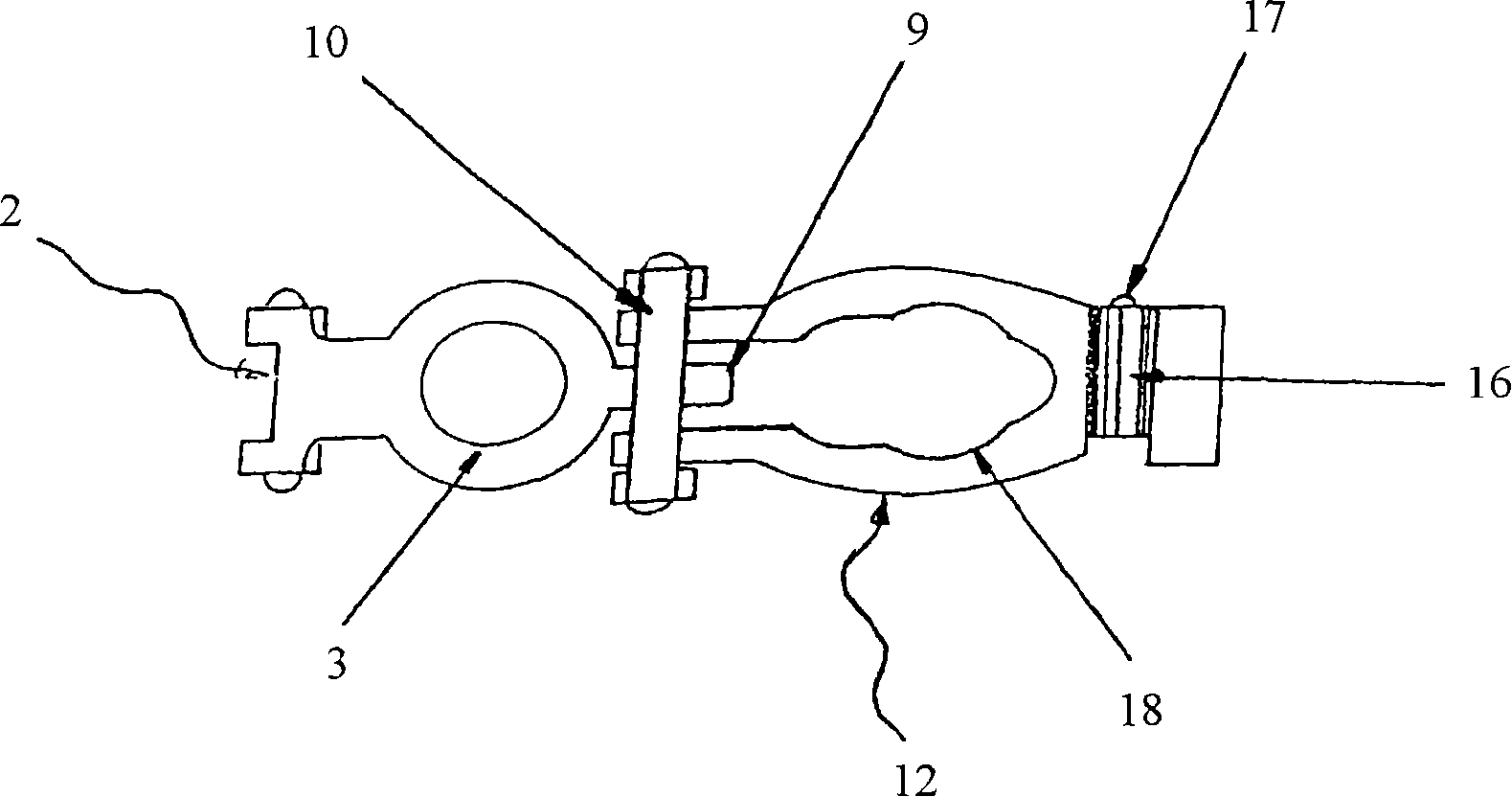
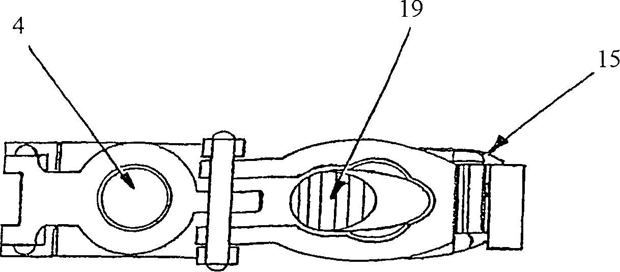
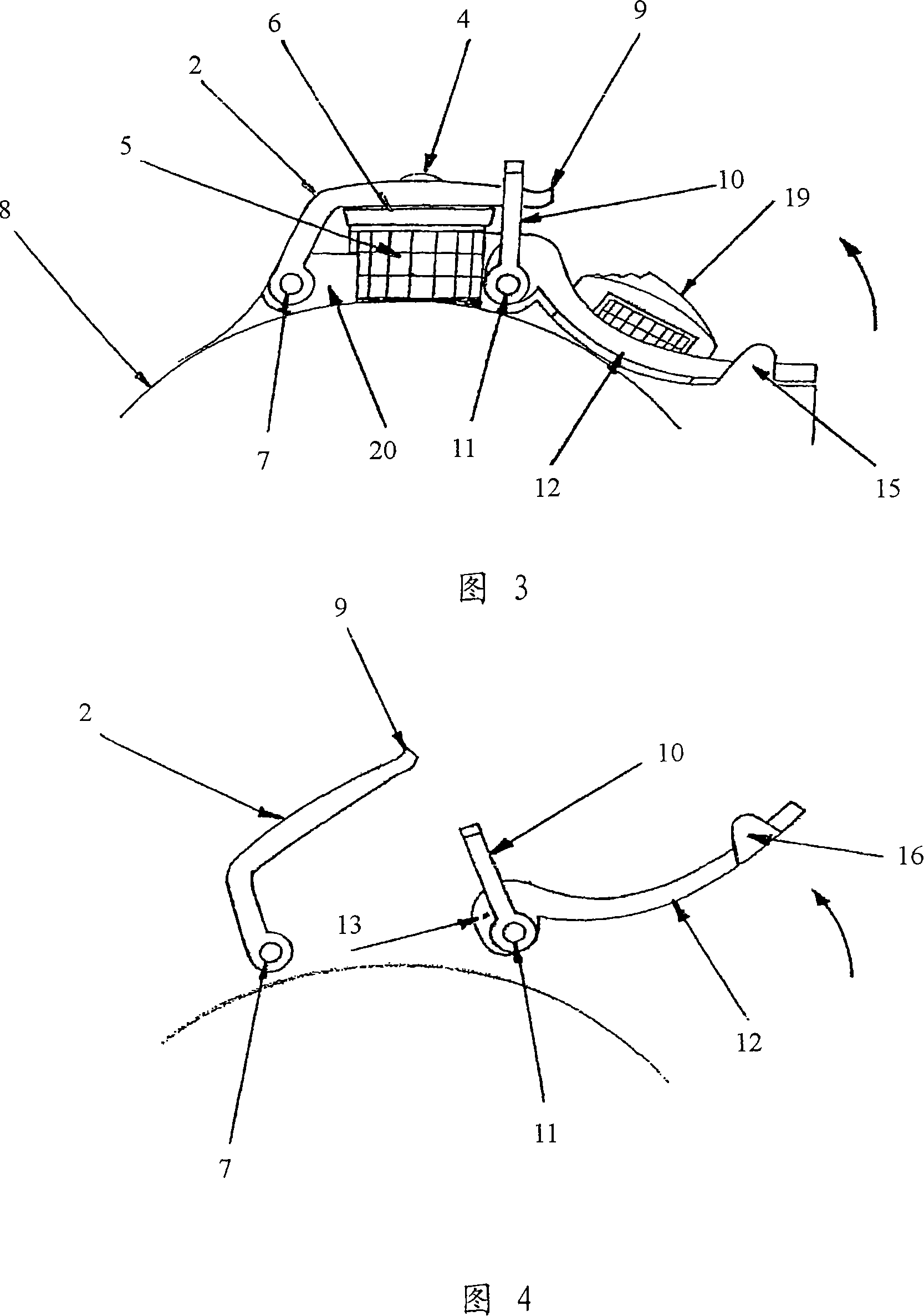
[0012] According to an embodiment of the invention, said sealing device 1 comprises a cap 2 having an annular portion 3 , and a fastening arm 12 . The annular part 3 of the cover 2 fits and rests against the seal 6 on the periphery of the cabochon 4 of the crown 5 , the cover 2 by means of two pivots recessed on each side of a shoulder 20 Pivoting on the first axis 7 , this shoulder 20 protects the crown 5 of the case 8 .

[0013] Closing lugs 9 are positioned on the end of the cover 2 . This lug 9 is designed to receive a clip 10 pivoted on a second axis 11 by means of two further pivots recessed on each side of the base of the fastening arm 12 . The fastening arm 12 itself is pivoted on the rod past another shoulder 14 that protects said crown 5 at the level of a third axis 13 , the second axis 11 relative to the pivot axis of said arm 12 A little eccentric.

[0014] When the securing arm 12 of the seal is disengaged from the case 8, the pivoting of said arm 12 on the thi...


PUM


Abstract

Provided is a MOS type solid state imaging device, including a semiconductor substrate, a plurality of pixels arranged on the semiconductor substrate, each pixel having a light receiving element for generating a signal charge due to incident light, and a MOS transistor for reading the signal charge, and a hydrogen supply film arranged on the semiconductor substrate over the plurality of pixels and having a region corresponding to the light receiving element at least a part of which has a film thickness greater than the other part of the region.

Description

technical field [0001] The present invention relates to the field of horology and in particular to a visible device which can have an original aesthetic appearance while guaranteeing an optimal sealing of the watch crown. Background technique [0002] Various systems for securing the sealing of the crown are already part of the prior art. Most systems use a seal located in the middle of the case. Threaded crowns are a widely used principle in dive watches. US5383166 discloses such a system comprising screwing a crown onto a thread provided on the outside of a tubular member threaded in the middle of the case, thereby compressing a seal arranged in said crown and sealing said crown . [0003] DE10109881 discloses a crown whose sealing is enhanced by fastening means which exert axial pressure on said crown. This means, integral with the rim, can be moved axially relative to the center of the watch, using said rim as a guide, in order to be able to enter the position opposi...

Claims


Application Information

Patent Timeline
Patent Type & Authority Patents(China)
IPC IPC(8): G04B3/04G04B37/10
CPCG04B3/043G04B37/10
Inventor 拉斐尔·科恩
Owner 拉斐尔科恩
Why Eureka
Try Eureka