Tungsten shorting stub and method of manufacture

A technology of short wires and tungsten alloys, which is applied in the direction of cable/conductor manufacturing, conductors, metal/alloy conductors, etc., which can solve the problems of increased overall size of short wires, unacceptable size and material costs, etc.

Inactive Publication Date: 2007-11-28
ANDREW CORP
View PDF1 Cites 2 Cited by
  • Summary
  • Abstract
  • Description
  • Claims
  • Application Information

AI Technical Summary

Problems solved by technology

[0006] For example, it is known that there is a limit in the 25-30KA range for shorting assemblies using conventional materials, unless the overall size of the shorting increases to the point where size and material cost are unacceptable

Method used


Image

  • Tungsten shorting stub and method of manufacture
  • Tungsten shorting stub and method of manufacture
  • Tungsten shorting stub and method of manufacture

Examples


Embodiment Construction

[0021] The electromechanical properties of tungsten and other metals and / or metal alloys are known as:

[0022] Material Conductivity Elasticity Tensile Yield Thermal Stability

[0023] (%IACS) (PSI) (PSI) (μin / in-℃)

[0024] (CTE) Bronze 28 16+10e 663,100 20.3

[0025] Phosphor bronze 16 16+10e6 74,700 16.0

[0026] Aluminum (7075) 33 10.3+10e6 73,000 23.2

[0027] Tungsten 30 59.5+10e6 109,000 4.6

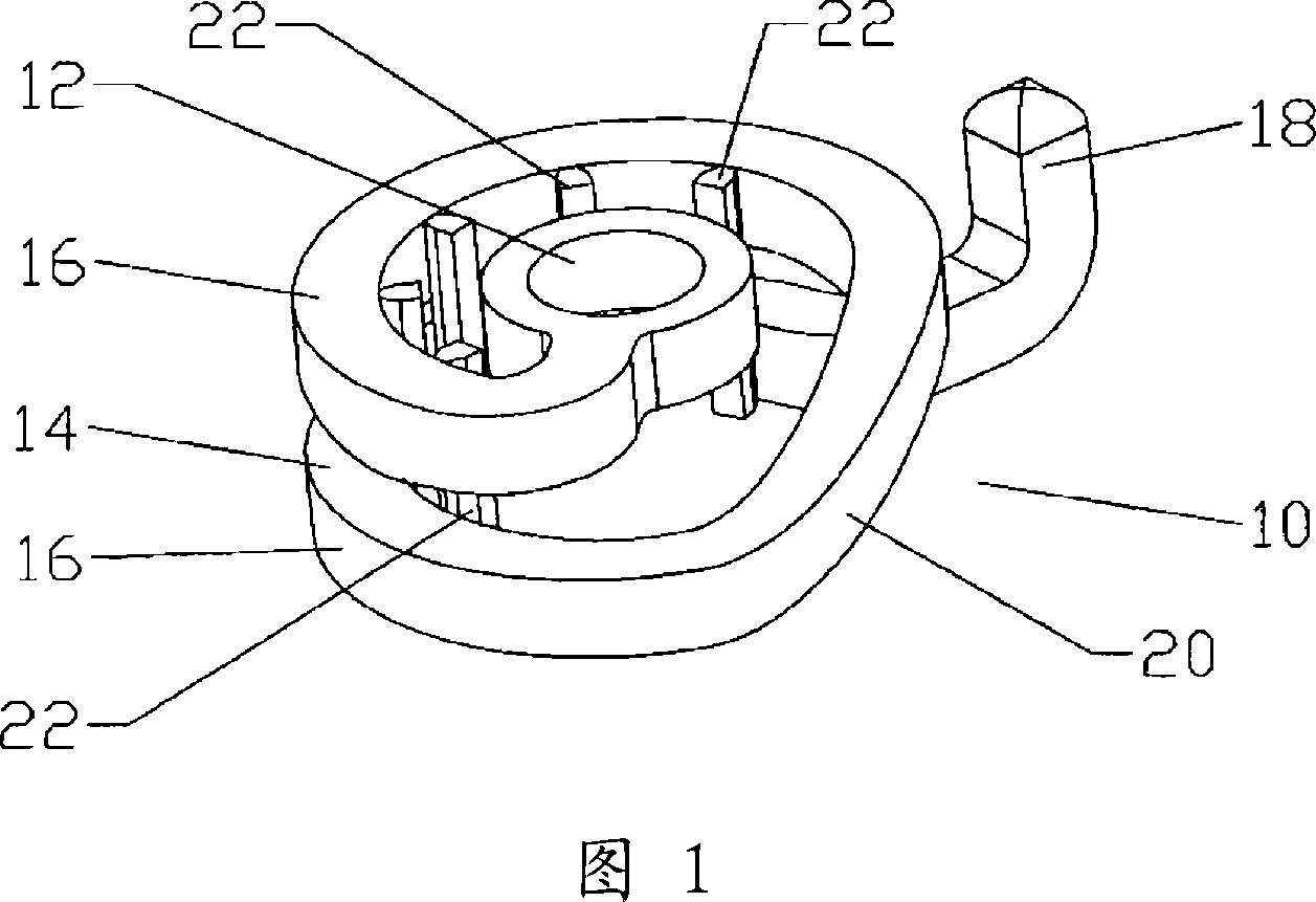
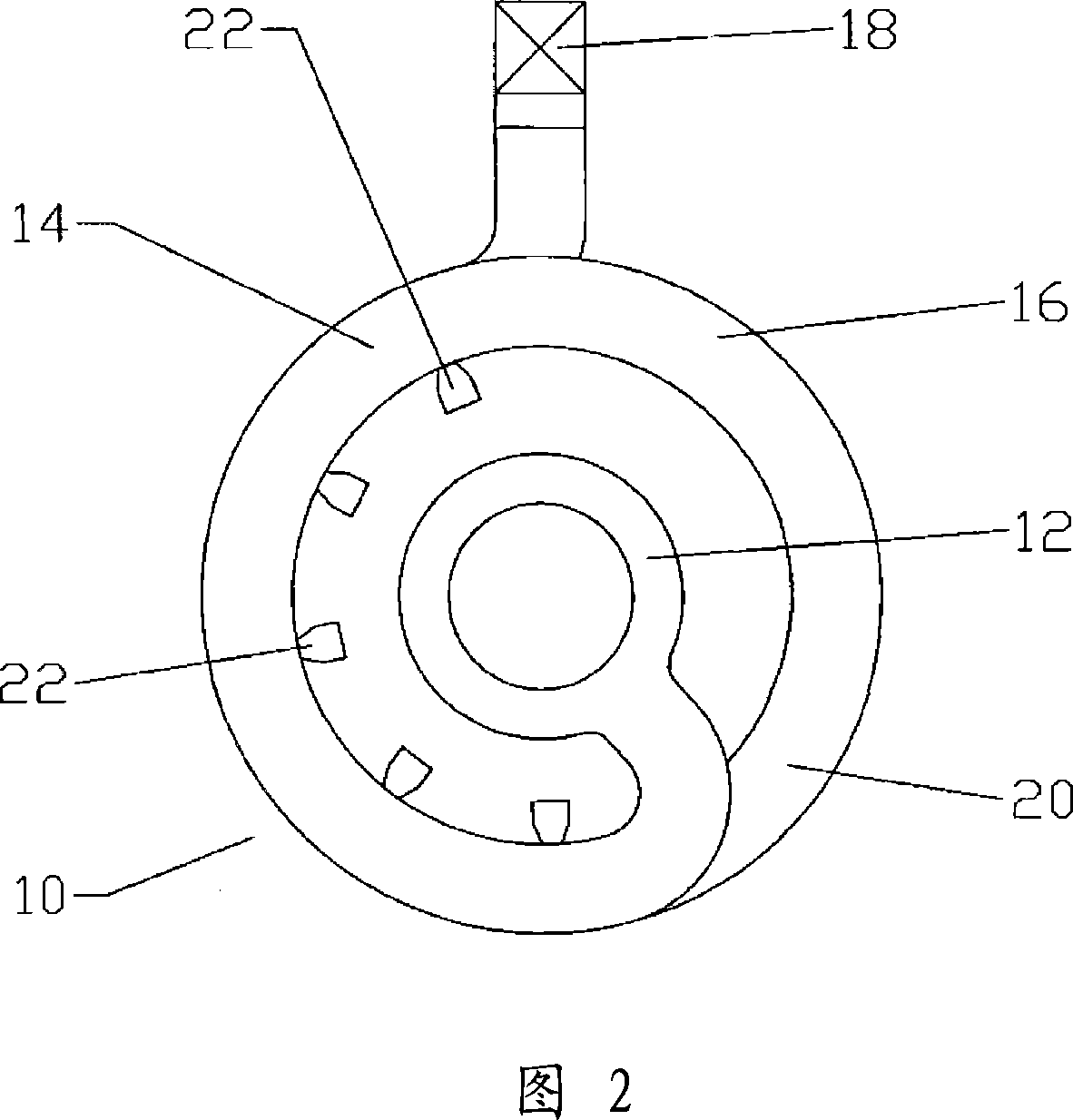
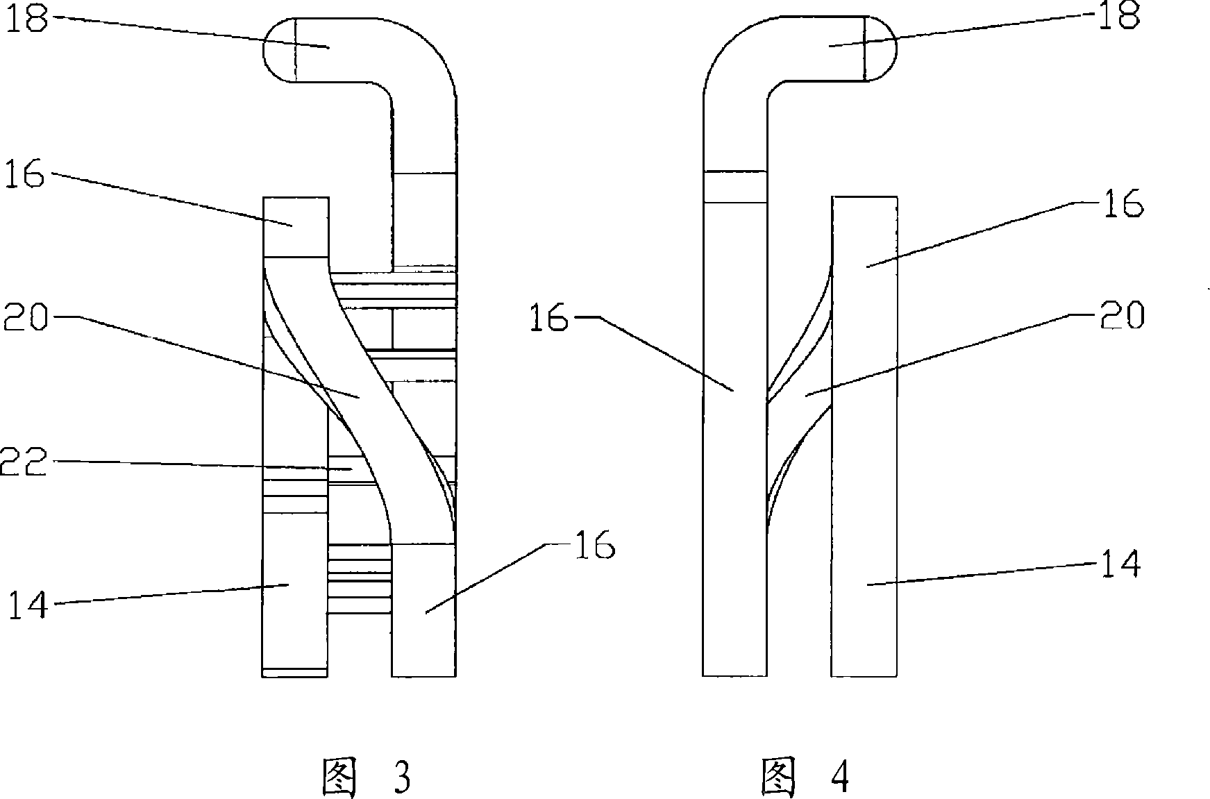
[0028] Although shorting wires can withstand relatively high power surge events, deformation of the shorting wires caused by the surge event can destroy the electrical performance of the working shorting wires. The inventors have recognized that, within the constraints of common assembly dimensions, a major limitation in designing shorts with higher surge resistance is the electromechanical properties of the materials used for the shorts.

[0029] While almost as conductive as aluminum (high conductivity is a desirable property because it reduces the resulting "...


PUM


Abstract

A shorting stub for connection between an inner conductor and an outer conductor of a coaxial cable. The shorting stub of a tungsten or tungsten alloy, having a connecting portion between an inner conductor connection and an outer conductor connection. The shorting stub may be cost effectively formed using metal injection molding techniques. The connecting portion may be formed by a plurality of loop segments in a range of different configurations. If needed, one or more supports may be applied to support the shorting stub during the metal injection molding.

Description

[0001] Horizontal citations to related applications [0002] This application claims the benefit of US Provisional Patent Application No. 60 / 747920, filed May 22, 2006 by Kendrick Van Swearingen and US Utility Patent Application No. 11 / 468708, filed August 30, 2006 by Kendrick Van Swearingen. technical field [0003] The present invention relates generally to improvements in the operating power level and overload capability of RF devices such as stubs for coaxial cables. In particular, the invention relates to improvements in the materials and production processes of these devices. Background technique [0004] The main limitation of helical and / or helical planar stub power regulation is the resistance to deformation when struck by lightning. The positive effect of the magnetic field produced by the interaction of the helical "coils" becomes a burden when the calculated geometry is deformed by the impact and the device is no longer electrically balanced in the frequency ran...

Claims


Application Information

Patent Timeline
IPC IPC(8): H01B5/00H01B1/02H01B13/00B22F3/115
Inventor 肯德里克·范斯韦林根
Owner ANDREW CORP
Why Eureka
Try Eureka