Supercharge Your Innovation With Domain-Expert AI Agents!

Structure d'enveloppe de protection pour un pilon

A protection cover and rammer technology, applied in the field of protection cover, can solve the problems of unstable posture, inability to work, easy to overturn, etc., and achieve the effects of elasticity, reduced damage, and prevention of damage to the prime mover

Active Publication Date: 2007-12-05
MIKASA SANGYO KK
View PDF1 Cites 4 Cited by
  • Summary
  • Abstract
  • Description
  • Claims
  • Application Information

AI Technical Summary

Problems solved by technology

[0002] The rammer is a construction including the rotary motion of the prime mover, and a telescopic leg and a rolling plate are provided under a crank chamber for converting the rotary motion into an up and down motion, so that the rolling plate is pressed at rest. In the state of being supported on the ground, the center of gravity of the body is located on the upper part of the body, the posture is unstable, and it is easy to fall over
Therefore, if the machine body is easy to fall over, there is a problem that the prime mover located on the upper part of the machine body and the important parts attached to it will collide with the ground and be damaged when the machine body is overturned, causing a situation where it cannot work

Method used


Image

  • Structure d'enveloppe de protection pour un pilon
  • Structure d'enveloppe de protection pour un pilon
  • Structure d'enveloppe de protection pour un pilon

Examples


Embodiment Construction

[0024] After the front end of the crank chamber side is joined to the peripheral portion of the front panel of the crank chamber, the protective cover supports the lower side of the prime mover on the support frame of the protective seat provided on the lower surface of the prime mover. Fix it on the support frame of the protective seat with bolts to complete the basic configuration operation of the protective covers on both sides, but for the sake of strengthening, it is better to insert the bolts from the outside of the vent hole to the inside of a part of the vent hole. Securely fix the protective cover on the wall of the crank chamber in the threaded hole.

[0025] (Example)

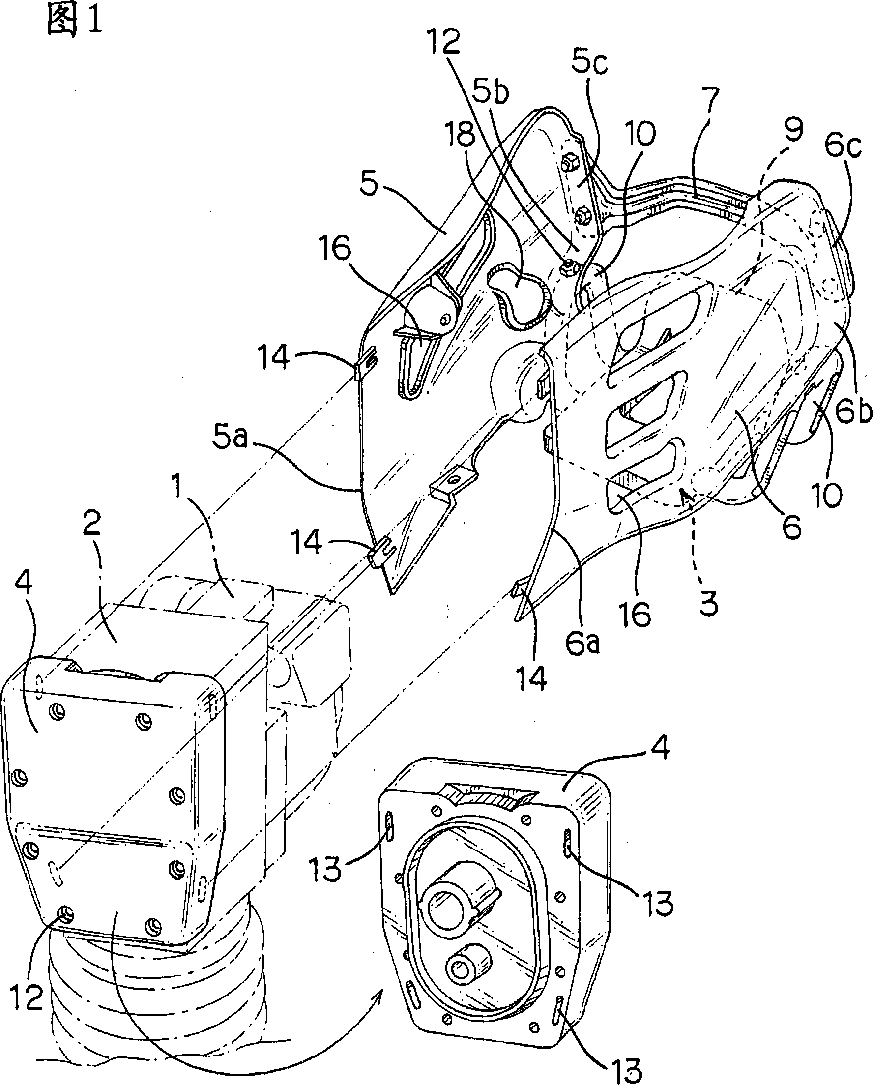
[0026] Next, the protective cover structure of the rammer involved in the present invention will be described with the help of the embodiment shown in FIG. 1. FIG. 1 is an axonometric view showing the basic composition of the protective cover structure. The protective cover structure includes: The p...


PUM


Abstract

To provide a rammer protective cover structure which is set up such that guard cover plates of a prime mover of a rammer are molded of a synthetic resin capable of forming an arbitrary shape and having imparted thereto lightweight properties, strength, and shock absorption, that the guard cover plates are assembled so as to be disassemblable by simple operation, and that the guard plates have imparted thereto durability against severe vibration, to thereby minimize the damage of a machine body by virtue of the adequate shock absorption even if the rammer is toppled.According to the rammer protective cover structure, the guard covers 5, 6 arranged on both sides of the prime mover 1 have their front edges 5a, 6a rigidly connected to a front surface of a crank chamber 2, and have their rear lower sides 5b, 6b supported by a support frame 10 of a protective mount 3 arranged on a lower surface of the prime mover 1. Then rear back surfaces 5c, 6c of the guard covers are connected together in one body by a connecting horizontal rod 7.

Description

technical field [0001] The present invention relates to an improvement in the guards protecting the crank chamber and prime mover of a rammer used to tamp a road surface by striking it with the up and down motion of the rolling plate. Background technique [0002] The rammer is a construction including the rotary motion of the prime mover, and a telescopic leg and a rolling plate are provided under a crank chamber for converting the rotary motion into an up and down motion, so that the rolling plate is pressed at rest. In the state supported on the ground, the center of gravity of the body is located at the upper part of the body, the attitude is unstable, and the body is prone to fall over. Therefore, if the machine body is prone to overturning, there is a problem that the prime mover located on the upper part of the machine body and the important parts attached thereto will collide with the ground and be damaged when the machine body is overturned, resulting in an inoperab...

Claims


Application Information

Patent Timeline
Patent Type & Authority Applications(China)
IPC IPC(8): E01C19/34
CPCE01C19/35E02D3/046
Inventor 田中义一原岛芳法永泽贤一村本健一
Owner MIKASA SANGYO KK
Features
  • R&D
  • Intellectual Property
  • Life Sciences
  • Materials
  • Tech Scout
  • Unparalleled Data Quality
  • Higher Quality Content
  • 60% Fewer Hallucinations
Learn More