

Damping component
A component and structure technology, which is applied in the direction of spring/shock absorber, vibration suppression adjustment, mechanical equipment, etc., can solve the problems that the natural vibration frequency cannot be consistent with the excitation frequency, the vibration reduction effect cannot be obtained, and the length of the vibration part is difficult to change.
- Summary
- Abstract
- Description
- Claims
- Application Information
AI Technical Summary
Problems solved by technology
Method used
Image

Examples
no. 1 Embodiment approach
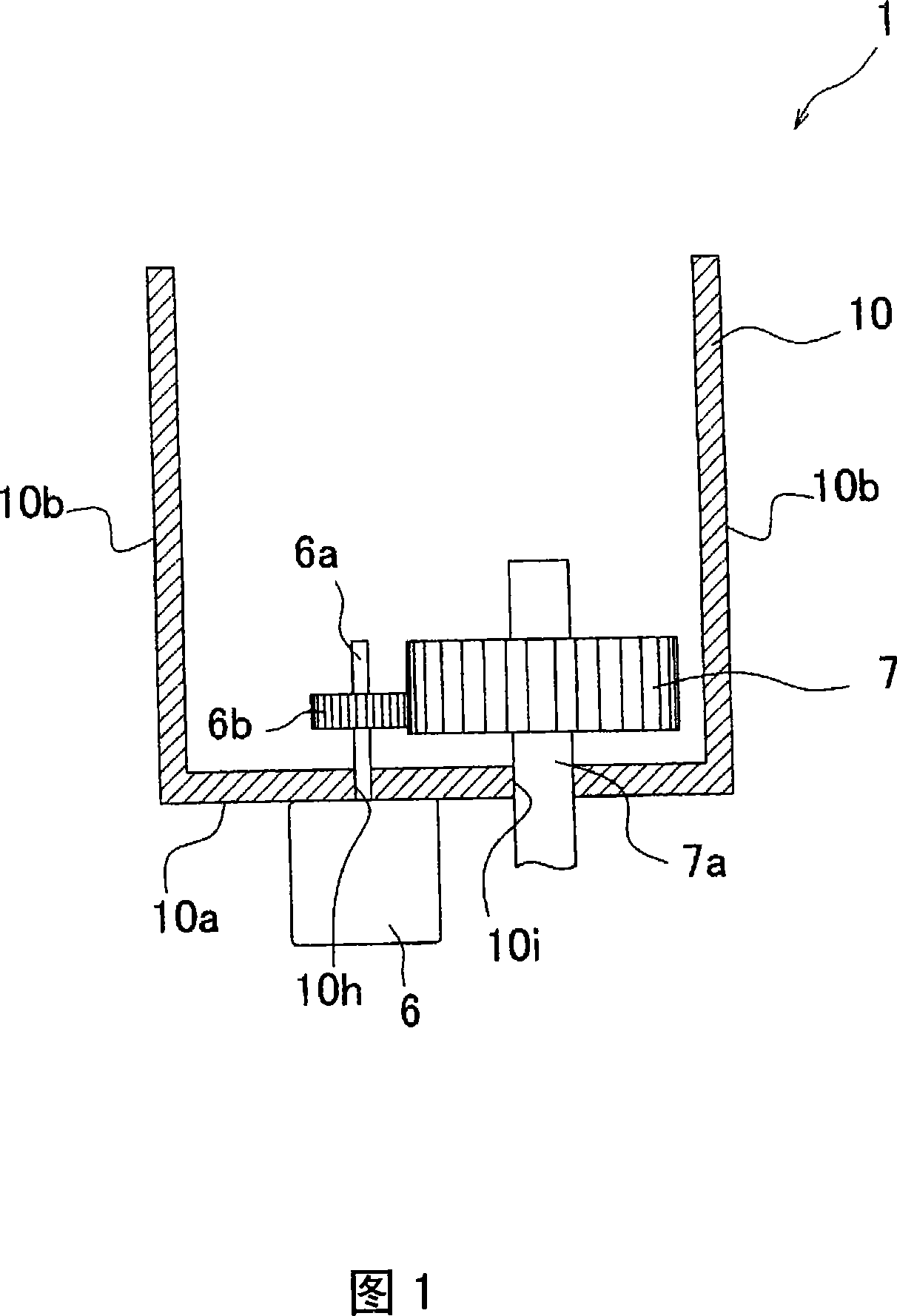
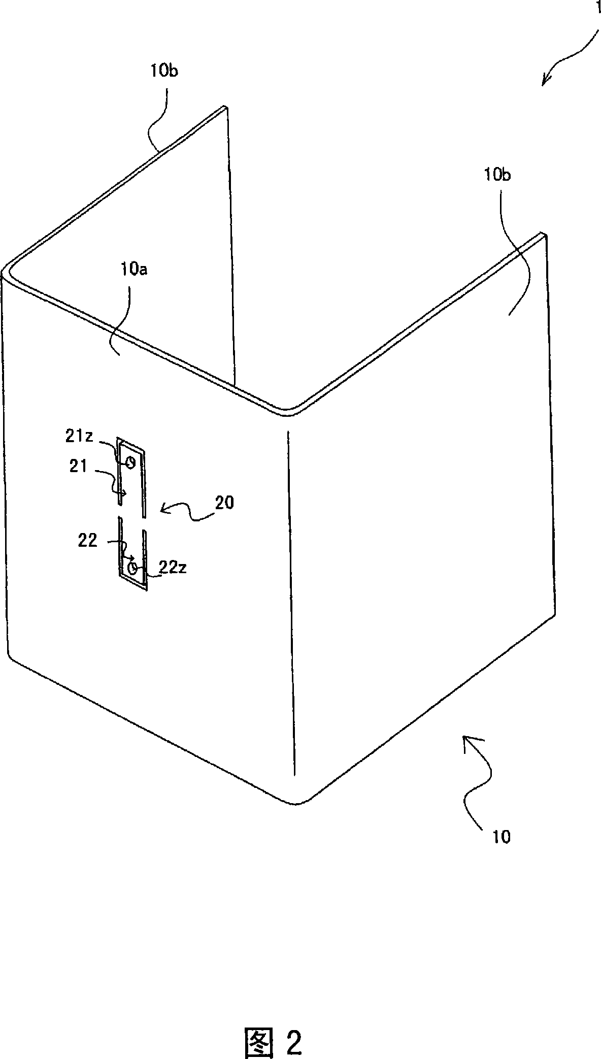
[0043] Next, a first embodiment of the present invention will be described with reference to FIGS. 2 and 3 . Fig. 2 is a perspective view showing the structure of the damping member of the present embodiment. In addition, in FIG. 2, the motor 6, the gear 7, and the shaft holes 10h and 10i are omitted.
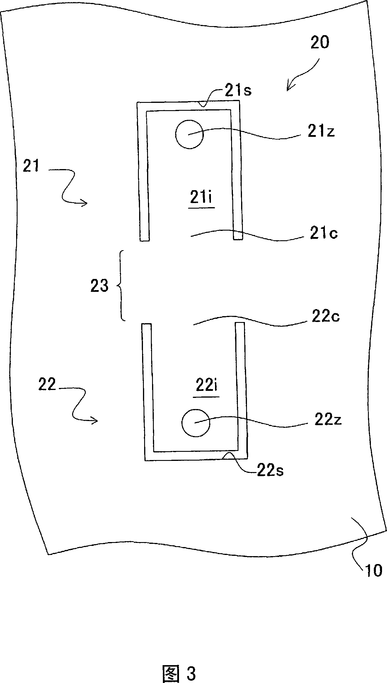
[0044] As shown in FIG. 2 , the main body portion 10 has a vibrating pair 20 . The vibrating pair 20 is formed by providing a cutout in the back surface 10a to reduce vibration in a direction perpendicular to the back surface 10a of the main body portion 10 due to the driving of the vibration device. FIG. 3 is an enlarged schematic front view of the vibrating pair 20 in FIG. 2 . As shown in FIG. 2 , a vibrating pair 20 is formed on the back surface 10 a of the main body 10 . As shown in FIG. 3 , the vibrating pair 20 has two vibrating parts 21 and 22, and the two vibrating parts 21 and 22 are respectively provided with two U-shaped cutouts 21s of the same shape passing throu...
no. 2 Embodiment approach
[0074] Next, a vibration damping member 100 according to a second embodiment will be described with reference to FIGS. 7 and 8 . As shown in FIG. 7 , the main body portion 110 has a vibrating pair 120 . The vibrating pair 120 serves to reduce the vibration of the main body part 110 vibrated by the driving of the vibrating device, and is formed by providing a cutout to the rear surface 110a.
[0075] FIG. 8 is a schematic enlarged front view of the vibrating pair 120 in FIG. 7 . As shown in FIG. 7 , the main body 110 is formed with a recessed portion 30 that sinks from the surface of the back surface 110 a toward the inside of the main body 110 , and the recessed portion 30 has an inclined surface 30 s as a part thereof. Here, directional vibrations are generated on the main body 110 due to the vibration of the vibrating device fixedly arranged on the main body 110 . The direction of the vibration (hereinafter, referred to as the vibration direction) is determined by the dire...
no. 3 Embodiment approach
[0094] Next, a third embodiment of the present invention will be described with reference to FIGS. 13 and 14 . Here, the description will focus on the parts that are different from the second embodiment. FIG. 13 is a perspective view of a vibration damping member according to this embodiment, and FIG. 14 is an enlarged schematic side view of the vibrating pair in FIG. 13 . In the vibration damping member 400 of the present embodiment, three recessed portions 431 , 432 , 433 are formed sinking from the back surface 410 a and the side surfaces 410 b , 410 b of the main body 410 toward the inside of the main body 410 . In addition, the recessed portions 431, 432, and 433 respectively have inclined surfaces 431s, 432s, and 433s as part thereof. In addition, the vibration direction (indicated by the arrow D in this embodiment) of the vibration generated by the vibration device coincides with the normal direction of the three inclined surfaces 431s, 432s, and 433s. In addition, U-...
PUM
 Abstract
Description
Claims
Application Information