Eureka AIR delivers breakthrough ideas for toughest innovation challenges, trusted by R&D personnel around the world.

Structure of steering wheel for vehicle

a steering wheel and vehicle technology, applied in the direction of shock absorbers, mechanical equipment, transportation and packaging, etc., can solve the problems of inability to secure a space for incorporating a large damper mass, inability to obtain inability to secure such a vibration damping effect, so as to achieve a sufficient vibration damping effect, increase the required installation space, and high efficiency of vibration damping

Inactive Publication Date: 2019-09-24
AUTOLIV DEV AB
View PDF13 Cites 1 Cited by
  • Summary
  • Abstract
  • Description
  • Claims
  • Application Information

AI Technical Summary

Benefits of technology

[0010]The present invention has been made in view of the problems of the conventional art, and an object of the present invention is to provide a vehicle steering wheel structure which, while having a configuration in which small damper masses are arranged in a distributed manner, can secure the same highly efficient vibration reducing effect as when a large damper mass is arranged, without increasing the required installation space and the cost.
[0015]In the vehicle steering wheel structure according to the present invention, although small damper masses are arranged in a distributed manner, it is possible to secure the same highly efficient vibration reducing effect as when a large damper mass is arranged without increasing the required installation space and the cost. By connecting the damper masses by the connection member, it is possible to obtain sufficient vibration damping effect with smaller total mass as compared to when small damper masses are just arranged in a distributed manner.

Problems solved by technology

When a damper mass is provided in a narrow space, it is difficult to secure a space for incorporating a large damper mass.
The individual small distributed damper masses cannot sufficiently damp vibration and it is not possible to secure such a vibration reducing effect as expected when a large damper mass is provided.
When a plurality of small damper masses is arranged, it is not possible to obtain a sufficient vibration damping effect with the mass corresponding to one large damper mass.
Moreover, if the weight is increased, the dimensions increase although the damper masses are small, and the required installation space also increases.
However, there is another problem in that the cost may increase if special material is used.

Method used


Image

  • Structure of steering wheel for vehicle
  • Structure of steering wheel for vehicle
  • Structure of steering wheel for vehicle

Examples


Embodiment Construction

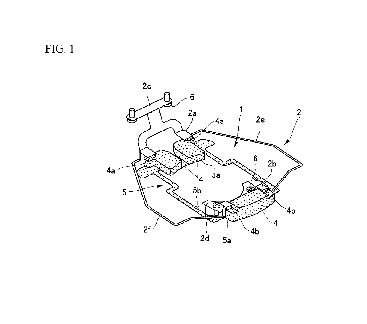
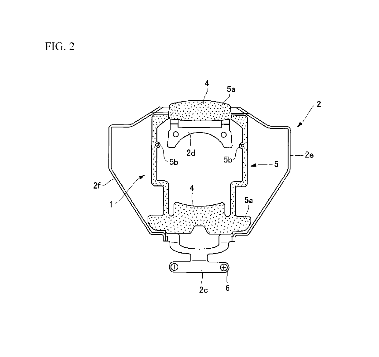
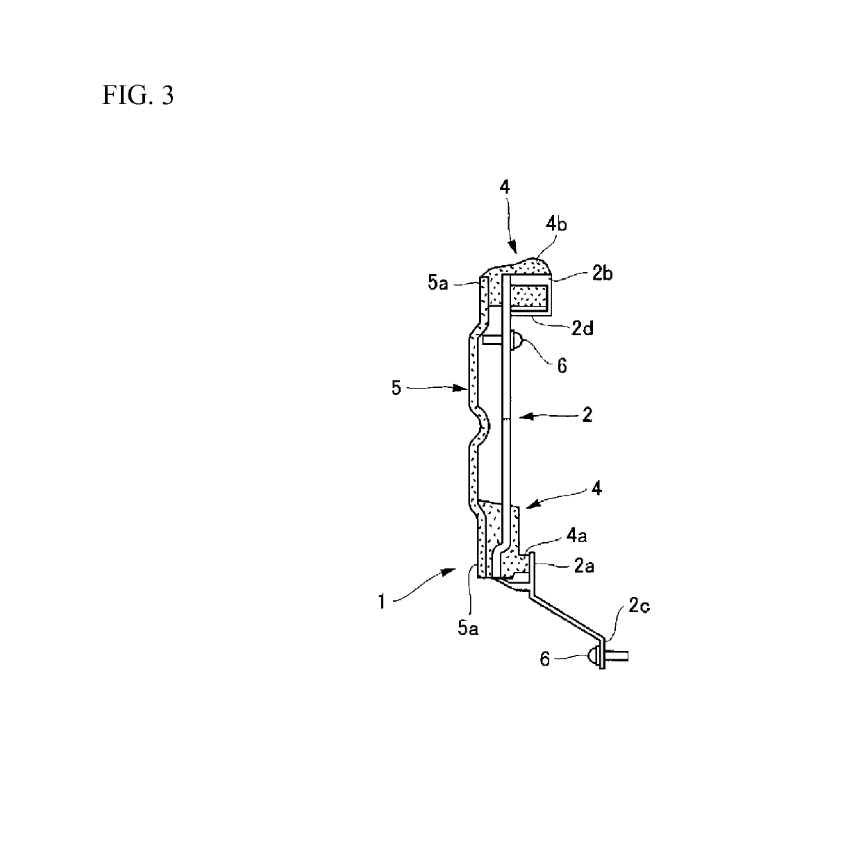
[0024]Hereinafter, a preferred embodiment of a vehicle steering wheel structure according to the present invention will be described in detail with reference to the accompanying drawings. FIGS. 1 to 3 illustrate a damper module 1 and a bracket 2 attached to the damper module 1. FIGS. 4 to 6 illustrate the bracket 2 in a state where the damper module 1 is incorporated into an inner region R of a rim portion 3a of a steering wheel 3.

[0025]As is well known, the steering wheel 3 includes a shaft coupling portion 3d coupled to a steering shaft, an annular rim portion 3a that surrounds the shaft coupling portion 3d, and spoke portions 3c and a shaft coupling peripheral region 3b that connect the rim portion 3a and the shaft coupling portion 3d.

[0026]The shaft coupling peripheral region 3b is a portion that continuously extends from the spoke portion 3c to the shaft coupling portion 3d, and is not clearly distinguished from the spoke portion 3c in particular but means a region which inclu...


PUM


Abstract

A vehicle steering wheel structure which, while having a configuration in which small damper masses are arranged in a distributed manner, can secure the same highly efficient vibration reducing effect as when a large damper mass is arranged, without increasing the required installation space and the cost. The vehicle steering wheel structure includes a plurality of damper masses arranged so as to be distributed in an inner region of a rim portion of a steering wheel; a connection member that connects these damper masses; and a damper module disposed in the inner region of the rim portion.

Description

BACKGROUND[0001]1. Field of the Invention[0002]The present invention generally relates to a vehicle steering wheel structure. More particularly, the invention relates to a vehicle steering wheel structure having a highly efficient vibration reducing effect.[0003]2. Description of Related Art[0004]In order to effectively reduce vibration of a steering wheel incorporated into a vehicle, it is necessary to provide a large (heavy) damper mass in the inner space of a rim portion of the steering wheel. The inner space of the rim portion of the steering wheel is very narrow because an airbag device, a horn component, a harness and the like are incorporated therein. When a damper mass is provided in a narrow space, it is difficult to secure a space for incorporating a large damper mass. Therefore, it is reasonable to arrange a plurality of small damper masses obtained by dividing the large damper mass, in a distributed manner. By doing so, it is possible to incorporate damper masses having ...

Claims


Application Information

Patent Timeline
Patent Type & Authority Patents(United States)
IPC IPC(8): F16F7/108F16F7/10B62D7/22
CPCB62D7/222F16F7/10F16F7/1028
Inventor KATO, YOUSUKEKUMAGAWA, HIROYASUSHIRAISHI, NORIHISA
Owner AUTOLIV DEV AB
Why Eureka
Eureka Blog
Learn More