Eureka AIR delivers breakthrough ideas for toughest innovation challenges, trusted by R&D personnel around the world.

Structure for mounting dynamic damper on rotary shaft and rotary shaft equipped with dynamic damper

Inactive Publication Date: 2008-07-24
TOKAI RUBBER IND LTD
View PDF2 Cites 7 Cited by
  • Summary
  • Abstract
  • Description
  • Claims
  • Application Information

AI Technical Summary

Benefits of technology

[0010]The present invention was made in the light of the above-described situation. It is therefore an object of the present invention to provide a structure for mounting a dynamic damper on a rotary shaft. In the mounting structure, a sufficient vibration damping effect can be obtained without unnecessarily increasing a mass of the mass member, even though the dynamic damper is mounted on the rotary shaft in such a manner that an axially center portion of a mass member is positioned axially apart from the position of a loop of bending vibration on the rotary shaft. It is another object of the invention to provide a rotary shaft equipped with a dynamic damper, in which the dynamic damper is mounted on the rotary shaft by employing the above mounting structure.
[0015]The above-indicated another object of the present invention may be attained cording to a second aspect of the present invention, which provides a rotary shaft equipped with a dynamic damper, the dynamic damper comprising (i) a mass member with a cylindrical shape mounted on the rotary shaft where vibration is occurred, and (ii) a first and second elastic support members respectively formed on axially opposite end portions of the mass member with a predetermined axial distance therebetween to elastically support the mass member and allow the mass member to be relatively displaced while the mass member is mounted on the rotary shaft, the dynamic damper being mounted on the rotary shaft, such that an axial center of the mass member is spaced axially apart from a position of a loop of the bending vibration on the rotary shaft, wherein the mass member has a center of gravity at a position deviated from the axial center thereof toward a first end of axially opposite ends, and, wherein the first and second elastic support members are fixed to the rotary shaft, upon the mass member being mounted on the rotary shaft such that an axial first section having the center of gravity of the mass member is located closer to the position of the loop of the bending vibration on the rotary shaft than an axial second section, whereby the dynamic damper is mounted on the rotary shaft.
[0017]In the structure for mounting a dynamic damper on a rotary shaft according to the first aspect of the present invention, although the axially center portion of the mass member is positioned axially apart from the position of the loop of the bending vibration on the rotary shaft, the dynamic damper is mounted on the rotary shaft in the state where the center of gravity of the mass member is either coincided with or maximally close to the position of the loop of the bending vibration thereon. This arrangement can advantageously provide the same or similar vibration damping effect as that obtained when the dynamic damper is mounted on the rotary shaft such that the axially center portion as the center of gravity of the mass member coincides with the position of the bending vibration loop thereon.

Problems solved by technology

Accordingly, even if the dynamic damper is attempted to be mounted on the rotary shaft so as to coincide the axially center portion of the mass member as the center of gravity thereof with the position of the bending vibration loop on the rotary shaft, the dynamic damper may contact or interfere with the other members arranged around the rotary shaft.
In consequence, there may be caused a problem of obstruction in mounting the damper on the above-described desired position.
When the dynamic damper is mounted at the position axially apart from the position of the bending vibration loop on the rotary shaft as described above, the vibration damping characteristic is inevitably deteriorated.
However, such methods increase not only the mass (weight) of the entire dynamic damper but also the mass (weight) of the rotary shaft equipped with the dynamic damper.
In addition, the size of the mass member become bigger, thereby a manufacturing cost of the dynamic damper is increased by the amount of increased mass thereof.
Furthermore, other problems are arisen such as a need for a larger space to mount the dynamic damper.

Method used


Image

  • Structure for mounting dynamic damper on rotary shaft and rotary shaft equipped with dynamic damper
  • Structure for mounting dynamic damper on rotary shaft and rotary shaft equipped with dynamic damper
  • Structure for mounting dynamic damper on rotary shaft and rotary shaft equipped with dynamic damper

Examples


Embodiment Construction

[0029]To further clarify the present invention, there will be described in detail embodiments of the invention with reference to the accompanying drawings.

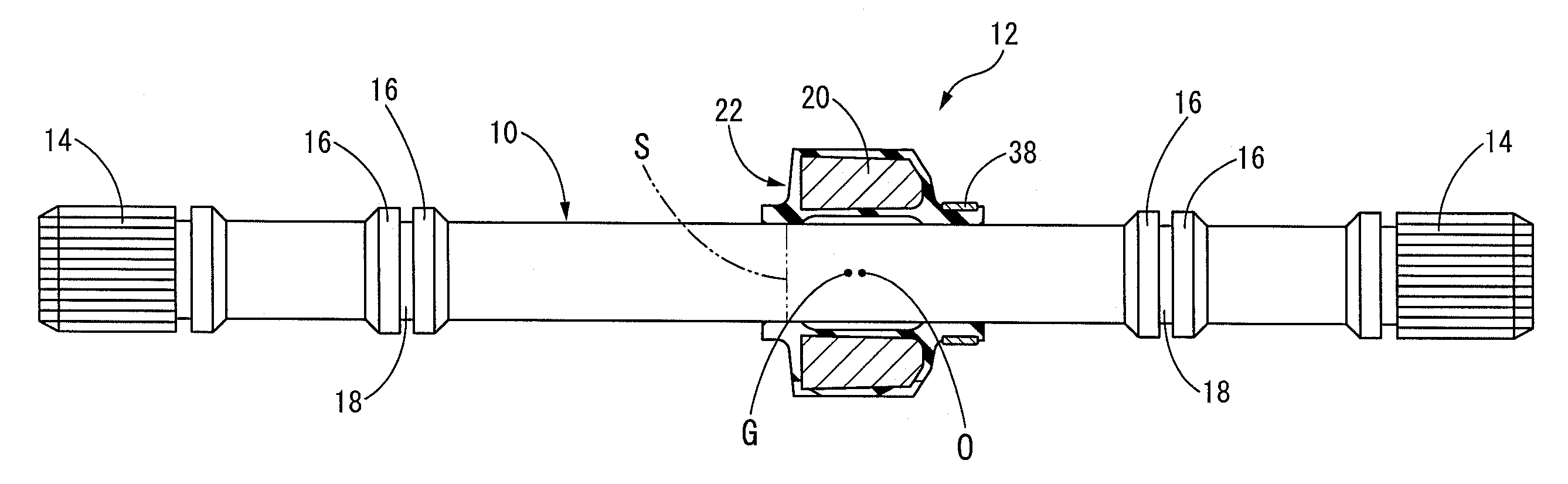
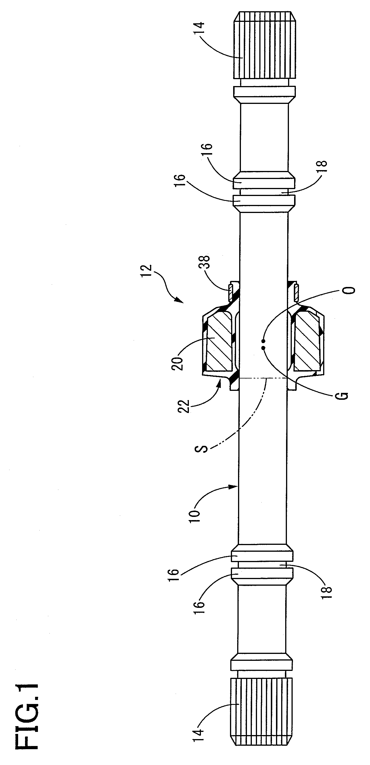
[0030]Referring first to FIG. 1, there is shown a front view showing a drive shaft equipped with a dynamic damper for an automobile as an embodiment of the rotary shaft with a dynamic damper mounted thereon according to a mounting structure of the present invention. In FIG. 1, only a dynamic damper 12 is shown in longitudinal cross section.

[0031]As apparent from FIG. 1, a drive shaft 10 is a generally long rod member which is hollow or solid and has a circular shape in transverse cross section. The drive shaft 10 integrally includes splined connecting portions 14, 14 having a large diameter at axially opposite ends thereof and two pairs of engaging portions 16, 16 each pair of which is formed axially inwardly of the respective connecting portions 14, 14 by a predetermined distance. Each pair of the engaging portions 16, 16 has a g...


PUM


Abstract

A structure for mounting a dynamic damper on a rotary shaft is disclosed. The dynamic damper comprises a mass member having a center of gravity at a position deviated from the axial center thereof toward a first end of axially opposite ends, and a first and second elastic support members which elastically support the mass member and allow the mass member to be relatively displaced. The mass member is mounted on the rotary shaft by fixing the first and second elastic support members to the rotary shaft, such that an axial first section having the center of gravity of the mass member is located closer to the position of the loop of the bending vibration on the rotary shaft than an axial second section, whereby the dynamic damper is mounted on the rotary shaft.

Description

[0001]The present application is based on Japanese Patent Application No. 2007-011290 filed on Jan. 22, 2007, the contents of which are incorporated herein by reference.BACKGROUND OF THE INVENTION[0002]1. Field of the Invention[0003]The present invention relates to a structure for mounting a dynamic damper on a rotary shaft and a rotary shaft equipped with a dynamic damper. More particularly, the invention relates to a structure for mounting a dynamic damper on a rotary shaft, in which the dynamic damper can advantageously be mounted at a portion axially apart from a position of a loop or an antinode of bending vibration on the rotary shaft where the bending vibration is occurred, and also relates to a rotary shaft equipped with a dynamic damper obtained by employing the mounting structure.[0004]2. Description of Related Art[0005]On rotary shafts such as a drive shaft and a propeller shaft of an automobile, to which bending vibration is applied, there is conventionally mounted a dyn...

Claims


Application Information

Patent Timeline
IPC IPC(8): F16F7/10
CPCY10T464/50F16F15/1442F16F15/10
Inventor HATANAKA, KEISHIKUWAYAMA, NAOHITO
Owner TOKAI RUBBER IND LTD
Why Eureka
Eureka Blog
Learn More