Ventilating air intake arrangement with mobile closing device

A technology of air intake device and closing device, which is applied in the cooling system of power plant, jet propulsion device, gas turbine device, etc., can solve problems such as excessive cooling, device failure, and inability to work normally, and achieves small negative effects and improved ventilation. Effect

Inactive Publication Date: 2010-06-16
AIRBUS OPERATIONS (SAS)
View PDF6 Cites 0 Cited by
  • Summary
  • Abstract
  • Description
  • Claims
  • Application Information

AI Technical Summary

Problems solved by technology

Due to the very low temperature of the outside air at cruising altitudes, these units are overcooled, resulting in the failure of these units to function
In addition, measurements have shown that when the aircraft is cruising, the air that circulates in this restricted area via the air ducts of the air intake is twice as much as required, so that in particular the full-authority numerical control mechanism of the engine is overcooled, resulting in its not working

Method used


Image

  • Ventilating air intake arrangement with mobile closing device
  • Ventilating air intake arrangement with mobile closing device
  • Ventilating air intake arrangement with mobile closing device

Examples


Embodiment Construction

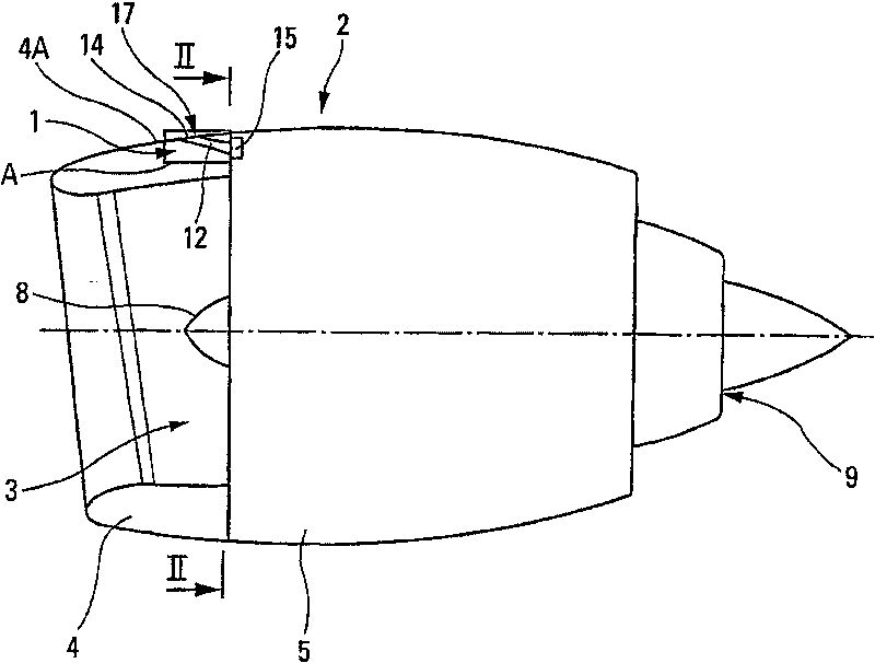
[0043] Depend on figure 1 The ventilation air intake device 1 of the present invention represented by middle rectangle A is located in the cabin 2 of an aircraft engine 3 such as a turbojet engine. Such as figure 1 As shown, the compartment 2 generally includes an intake front 4 that feeds air to the engine, a middle 5 that surrounds the fan 8, engine compressor, combustor and turbine casing 7, from which the casing of the nozzle 9 and its cone stick out.

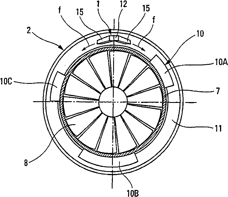
[0044] On the housing 7 of the fan and compressor, ie in the annular confined space or area 11 between the nacelle 2 and the housing 7 of the engine 3, various mechanical and / or electrical devices or pieces of equipment 10 are mounted. figure 2Some of the devices 10 located in this zone 11 are illustrated, namely the engine full authorization digital control mechanism 10A, the gearbox 10B and the engine oil tank 10C.

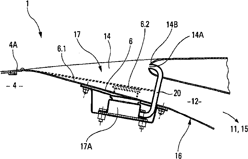
[0045] The ventilation air intake 1 located on top of the front 4 of the cabin 2 ensures the ventilati...


PUM


Abstract

The invention concerns a ventilating air intake arrangement with mobile sealing device. The arrangement comprises at least one air passage channel (12) with an air vent (14), and is designed to ventilate at least one confined zone (11) in an aircraft with fresh air entering upstream, through the air vent, in the channel and exiting downstream thereof towards the zone to be ventilated. The invention is characterized in that the cross-section of the air passage channel (12) is automatically adjustable based on the speed and the altitude of the aircraft and the arrangement comprises therefor controllable mobile-element closing means (17) associated with the channel and for varying its cross-section.

Description

technical field [0001] The present invention relates to a ventilation intake device comprising an air duct having a vent for ventilating at least one restricted area in a vehicle such as an aircraft. Background technique [0002] It is well known that this type of ventilation intake device is widely used in the aviation field to ventilate an area with heat-sensitive equipment and / or dangerous flammable and explosive materials around it. To prevent equipment failure or fire and explosion, it is necessary to ensure the continuity of this area. ventilation. [0003] This is especially the case when a number of mechanical and / or electrical devices are located in the annular confined zone between the nacelle of the aircraft turbojet engine and the housings of the fans and compressors. Devices such as engine full authority digital controls, gearboxes, engine oil tanks, fluid components, etc., which are usually fixed around the housing so as to be located in the restricted area, a...

Claims


Application Information

Patent Timeline
Patent Type & Authority Patents(China)
IPC IPC(8): F02C7/042
CPCB64D2241/00B64D33/08
Inventor A·波特D·普拉特
Owner AIRBUS OPERATIONS (SAS)
Why Eureka
Try Eureka