Adjusting device for rotating mould

A technology of adjusting device and rotating module, applied in the direction of large fixed members, metal processing machinery parts, metal processing equipment, etc., can solve the problem of reducing the positioning accuracy between racks 1 and 2, etc.

Inactive Publication Date: 2007-12-12
HONG FU JIN PRECISION IND (SHENZHEN) CO LTD +1
View PDF0 Cites 4 Cited by
  • Summary
  • Abstract
  • Description
  • Claims
  • Application Information

AI Technical Summary

Problems solved by technology

[0003] However, the rotating module 3 reduces the positioning accuracy between the racks 1, 2 while reducing the damage to the racks 1, 2

Method used


Image

  • Adjusting device for rotating mould
  • Adjusting device for rotating mould
  • Adjusting device for rotating mould

Examples


Embodiment Construction

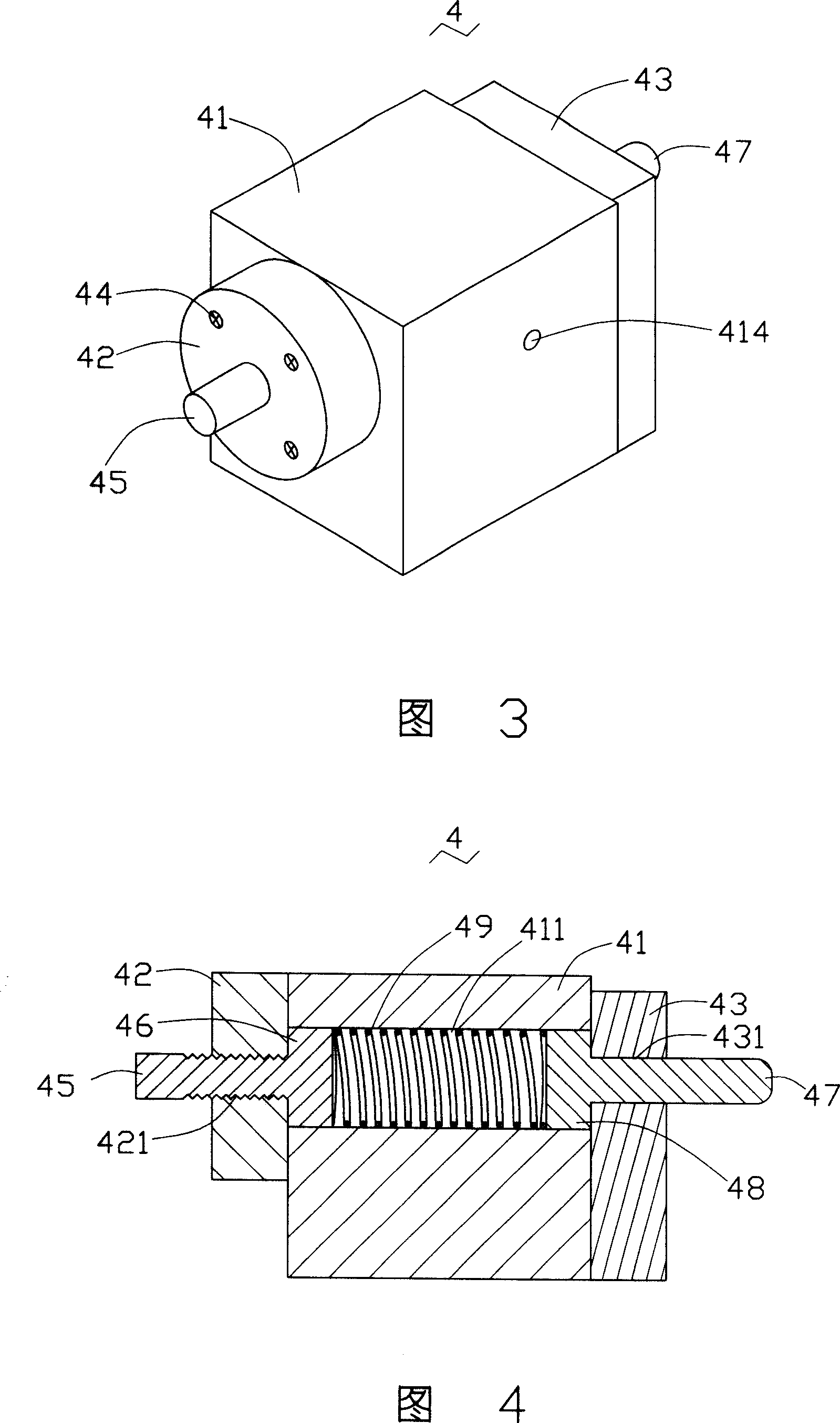
[0014] The present invention will be further described in detail below in conjunction with the accompanying drawings.

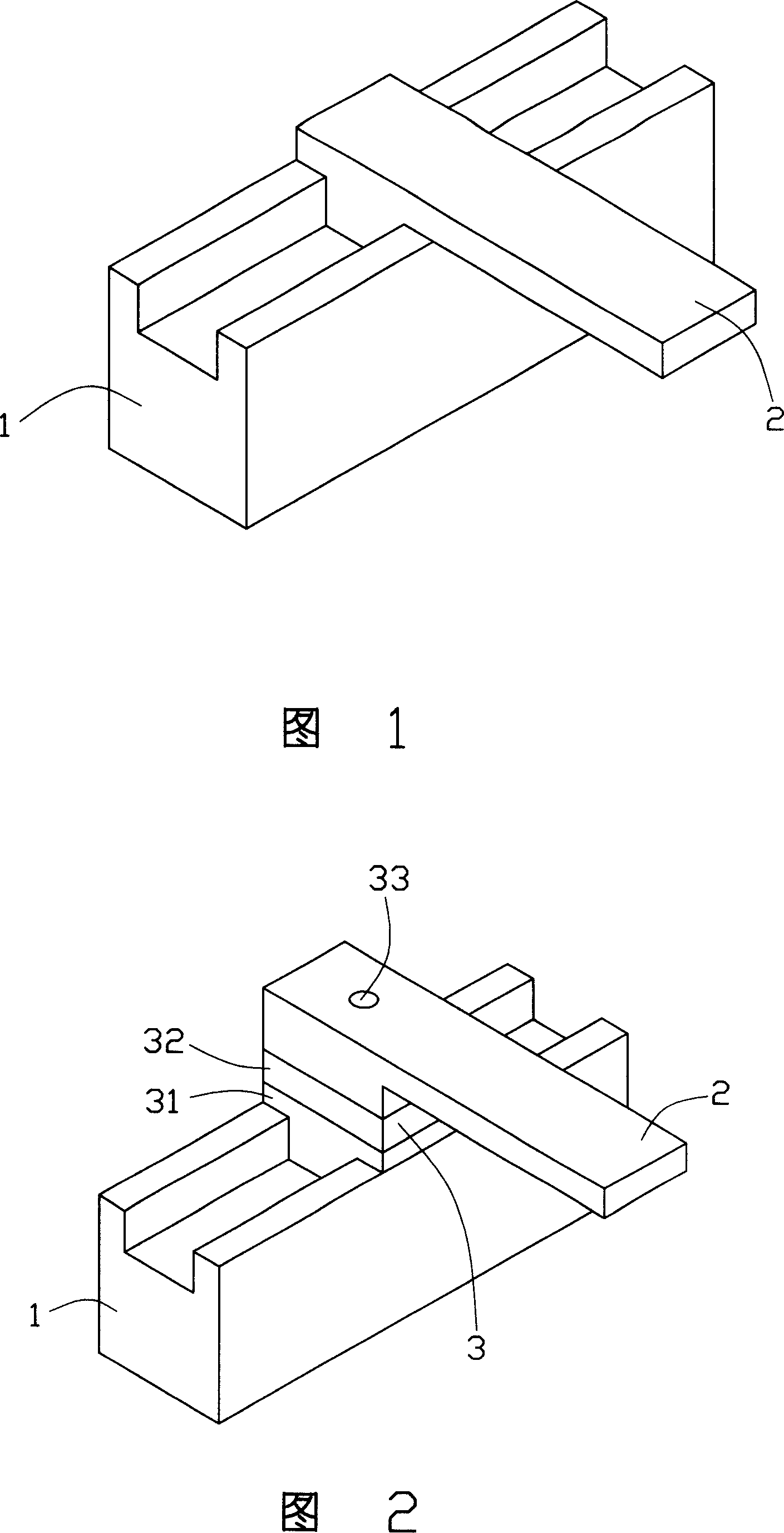
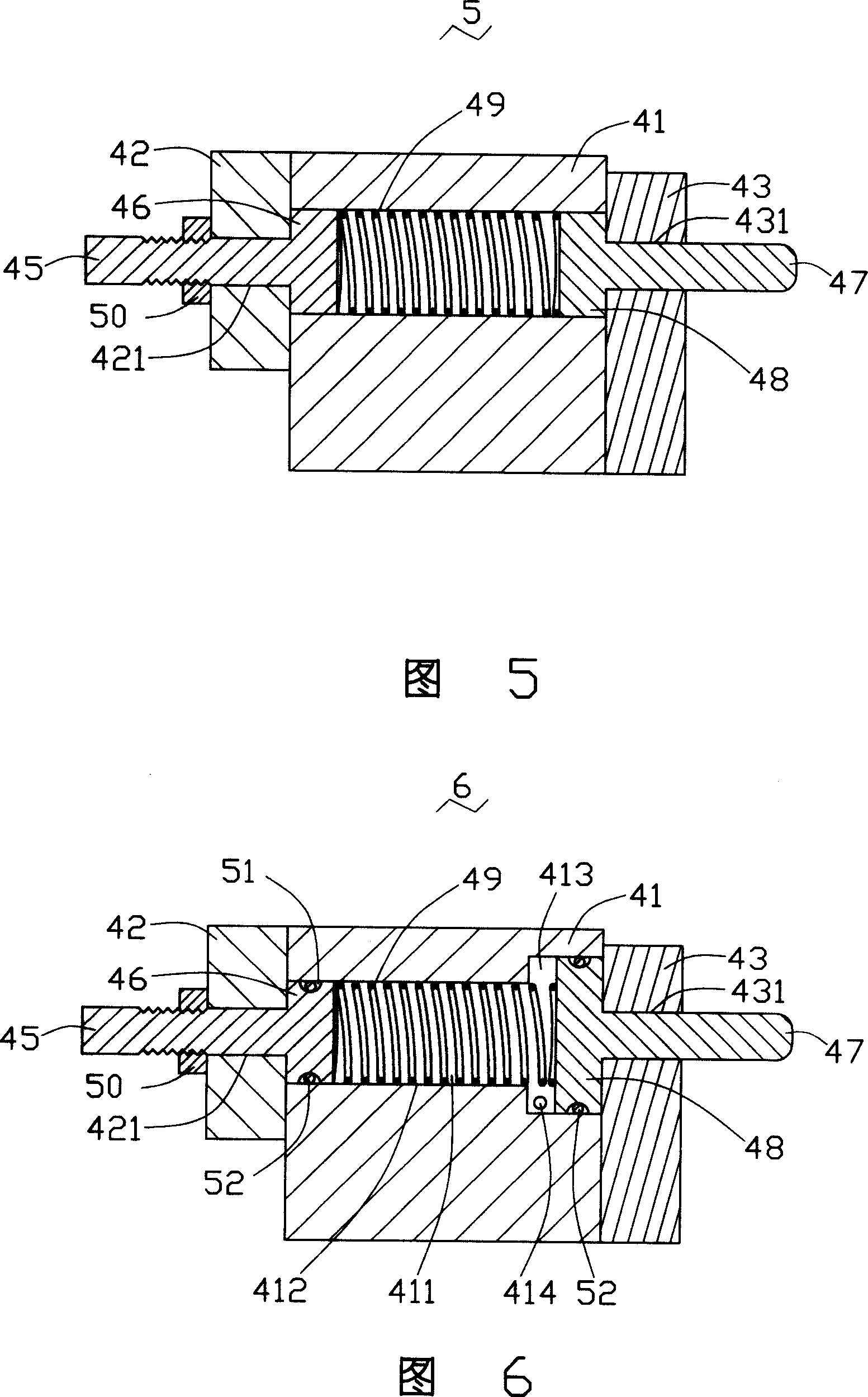
[0015] Please refer to FIG. 3 to FIG. 4 , the first embodiment of the present invention provides an adjusting device 4 for a rotary module, which includes: a housing 41 having a through hole 411 ; a first blocking portion 42 , the The first blocking portion 42 is provided with a first through hole 421; a second blocking portion 43 is provided with a second through hole 431, and the first blocking portion 42 and the second blocking portion 43 are connected by at least one screw 44 Or its equivalent components are respectively fixed on the two ends of the through hole 411 of the housing 41; an adjustment rod 45, the adjustment rod 45 is stretched out of the housing 41 from the first through hole 421, and a first piston 46 is fixed on the adjustment rod 45. One end of the rod 45 is located in the through hole 411. When the adjusting rod 45 moves, the first pisto...


PUM


Abstract

The invention relates to a rotary module adjustment device that comprises a shell with a through hole, the first and second baffle parts with the first and second through holes respectively, the first and the second baffle parts fixed at both ends of the through hole of the shell, an adjustment bar sticking out of the shell from the first through hole, a first piston fixed at one end inside the through hole of the adjustment bar, a leaning against bar sticking out of the shell through the second through hole, the second piston fixed at one end of the leaning against bar inside the through hole, a spring shrinking between the first and the second pistons with its length adjustable through the adjustment bar. It can be used to adjust the rotary scope and precision of the rotary module.

Description

【Technical field】 [0001] The invention relates to an adjusting device for a rotary module, in particular to an adjusting device for the rotating module of a gantry machine. 【Background technique】 [0002] A frame 1 of a traditional gantry machine is connected to another frame 2 by being embedded or externally embedded in a slideway as shown in FIG. 1 , so that the two frames 1 and 2 can slide relative to each other. When the two frames 1, 2 slide relatively, it is likely that the frames 1, 2 will be damaged due to uneven force or excessive resistance. As shown in Figure 2, adding a rotating module 3 at the junction of the two frames 1 and 2 can reduce this damage. The first part 31 of the rotating module 3 is slidably connected with the frame 1, and the second part of the rotating module 3 32 is fixed to another frame 2, and the first part 31 and the second part 32 are connected by a pivot 33 and can rotate relative to each other. [0003] However, the rotating module 3 re...

Claims


Application Information

Patent Timeline
Patent Type & Authority Applications(China)
IPC IPC(8): B23Q1/25B23Q1/26B23Q1/48B23Q1/01
Inventor 胡兴亿
Owner HONG FU JIN PRECISION IND (SHENZHEN) CO LTD
Why Eureka
Try Eureka