Table top positioning mechanism for plate drilling machine

A positioning mechanism and drilling machine technology, applied in stone processing tools, stone processing equipment, manufacturing tools, etc., can solve the problems of easy penetration and breaking, and achieve the effect of stable support

Inactive Publication Date: 2007-12-12
苏州工业园区科特建筑装饰有限公司
View PDF0 Cites 13 Cited by
  • Summary
  • Abstract
  • Description
  • Claims
  • Application Information

AI Technical Summary

Problems solved by technology

[0004] The invention provides a table positioning mechanism of a plate drilling machine, the purpose of which is to solve the problem that the existing drilling machine table is easy to penetrate and break through the thin plate drilling

Method used


Image

  • Table top positioning mechanism for plate drilling machine
  • Table top positioning mechanism for plate drilling machine
  • Table top positioning mechanism for plate drilling machine

Examples


Embodiment

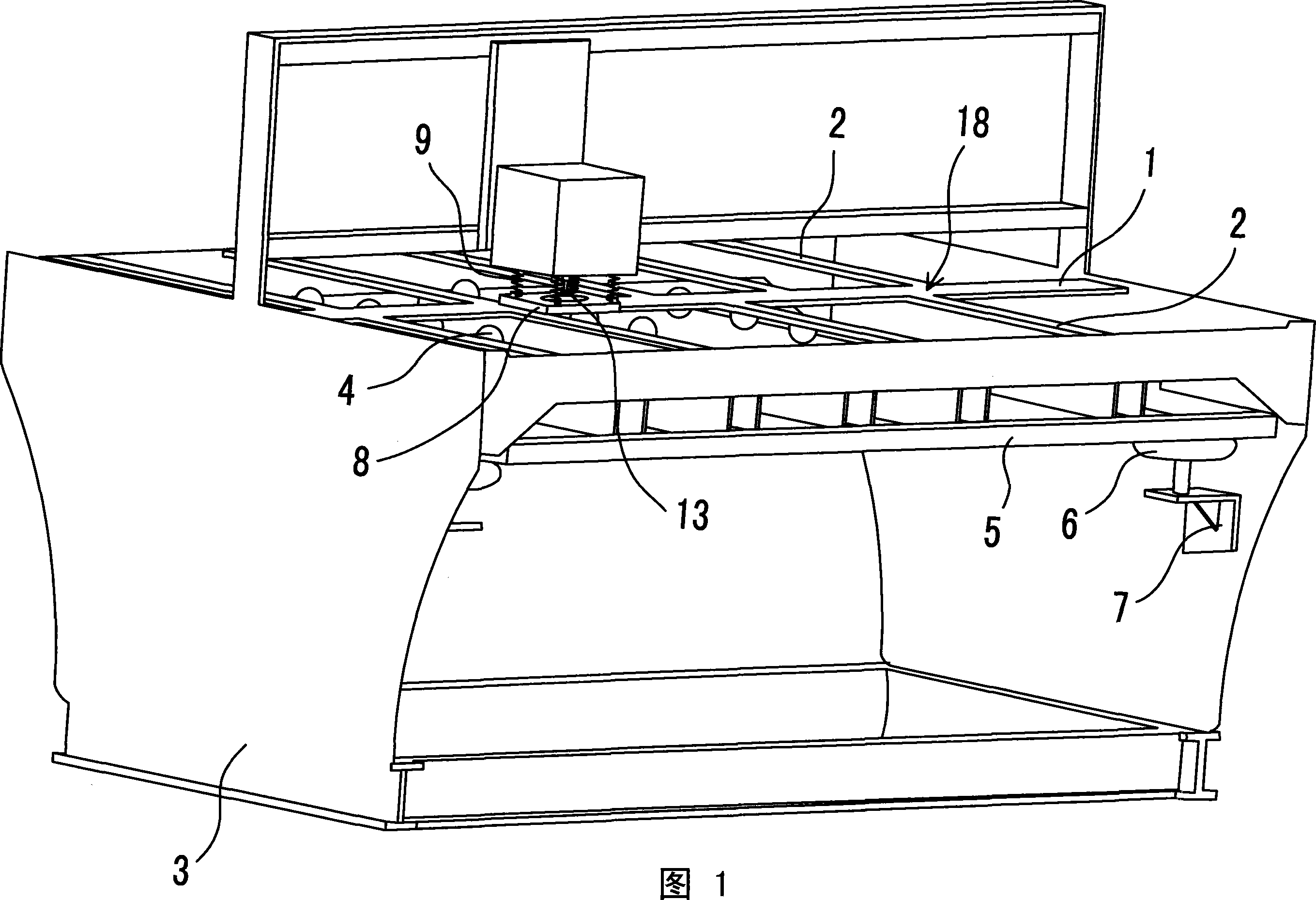
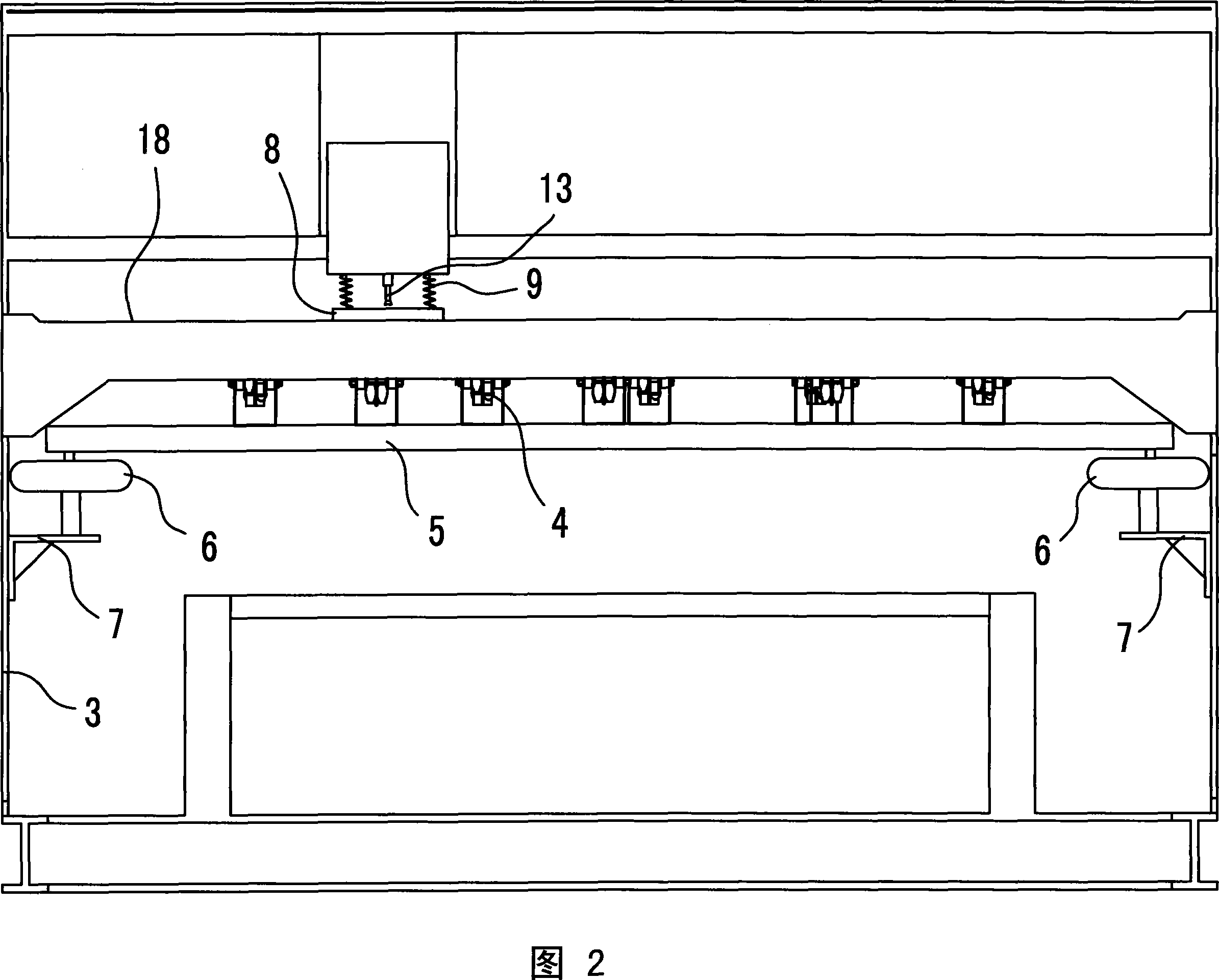
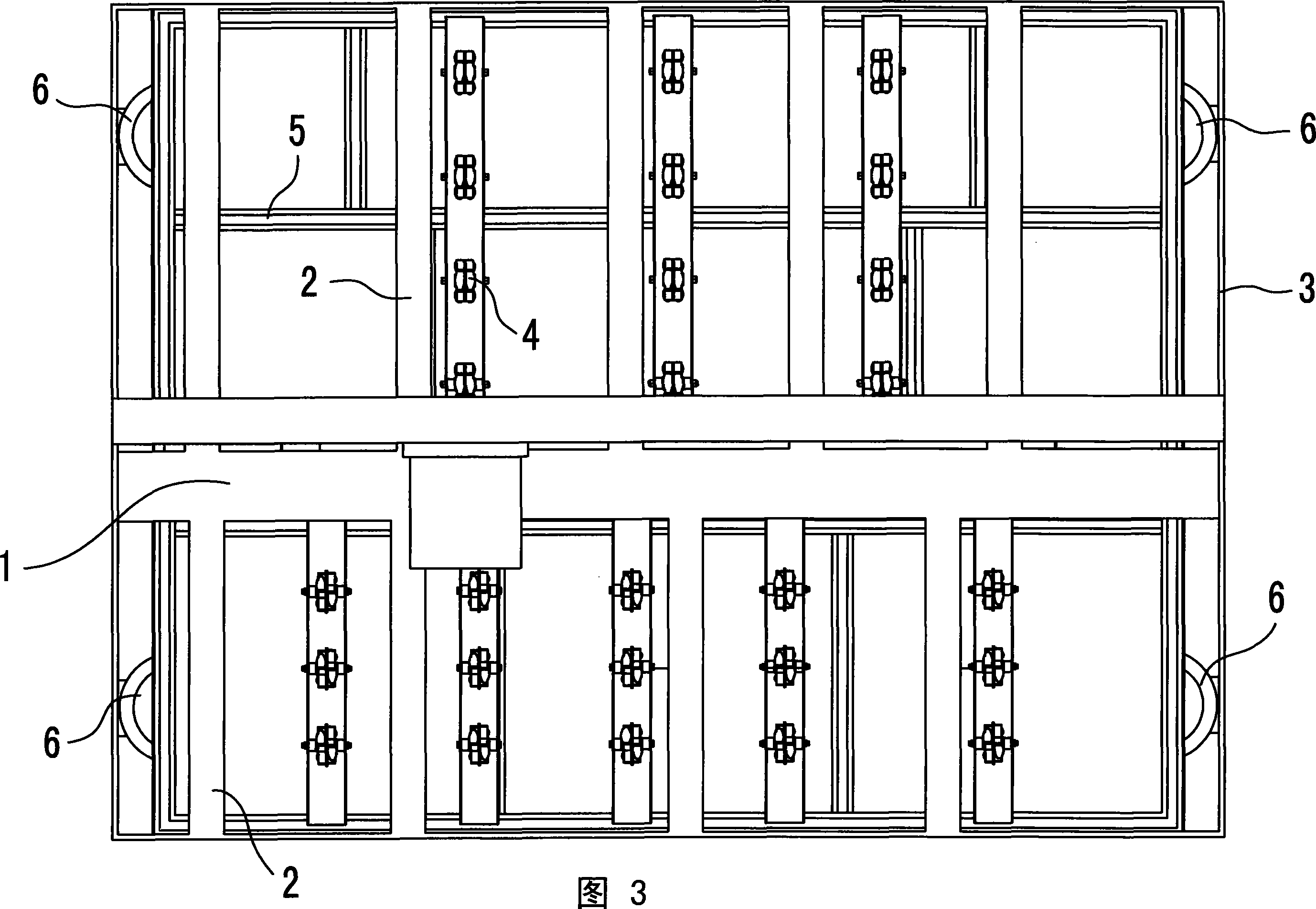
[0029] Embodiment: A table positioning mechanism suitable for a fully automatic or semi-automatic plate drilling machine is composed of three parts: a plate horizontal support mechanism, an elastic platen pressing mechanism and a plane positioning mechanism.

[0030]As shown in Fig. 1, Fig. 2 and Fig. 3, the horizontal support mechanism for the plate is composed of a dislocation combination of a fixed support table 18 and a lifting roller support table. The fixed support table 18 is provided with a main support plate 1 arranged along the X direction (horizontal and transverse direction of the front of the complete machine), and the main support plate 1 is located directly below the drill bit 13 in the Y direction (horizontal and longitudinal direction of the front of the complete machine), so that the drill bit 13 can punch holes. When the action point falls on the main support plate 1 all the time, in other words, the main support plate 1 bears the horizontal support function ...


PUM


Abstract

The table positioning device features in the elastic press board as the drilling surface on the plate horizontally, with the center of the press board providing drilling head going through the hole, support machine of the plate made of the table and the alight rolling wheel support table, with the fixed support table having main support plate along X axis, auxiliary support along Y axis at both sides of the main support plate, with adjacent assisted support plate forming into ÀÃ perforated fixed support table with horizontal and isolation device, with the alight rolling support table made of a set of universal rolling wheel supported by the support frame, support frame and alight device in up and down working status relative to the fixed support table for each wheel edge formed rolling surface face. It can solve the through and broken issue of drilling thin plate, being able to drill 7mm blind hole on the 9mm ceramic plate.

Description

technical field [0001] The invention relates to a plate drilling machine for back-cut anchoring wall decorative panels, in particular to a table positioning mechanism for clamping a plate to be drilled on the plate drilling machine. Background technique [0002] With the development of the building decoration industry, the appearance of urban buildings is not only the pursuit of shape, more buildings begin to pay attention to the beauty, practicality and environmental protection of the exterior wall decoration, so curtain wall panels are adopted by more and more construction companies . At present, the curtain walls of urban buildings mostly use decorative plates such as slate, ceramic plates or microcrystalline slabs, and the fixing methods are mostly back-cut anchoring installations. Back-cut anchoring installation needs to drill blind holes (not pierced) on the back of the decorative plate on site, so that the back-cut anchors and L-shaped anchors can be used to hang and...

Claims


Application Information

Patent Timeline
Patent Type & Authority Applications(China)
IPC IPC(8): B28D1/14
Inventor 吴斌陆锋
Owner 苏州工业园区科特建筑装饰有限公司
Why Eureka
Try Eureka