Check patentability & draft patents in minutes with Patsnap Eureka AI!

Network frequency width monitoring adjustment system

A system and bandwidth adjustment technology, applied in the field of network bandwidth monitoring and adjustment systems, can solve problems such as competing bandwidth, insufficient bandwidth, packet data loss, etc.

Inactive Publication Date: 2007-12-12
AMROAD TECH
View PDF0 Cites 0 Cited by
  • Summary
  • Abstract
  • Description
  • Claims
  • Application Information

AI Technical Summary

Problems solved by technology

[0002] In modern times with advanced technology, the network is like the nerves of the human body, connecting the reactions of various organs in the human body together. Because of this, packet loss is easy to occur during network transmission. There are mainly three types of network packet loss The first reason is: general packet loss, because the network is an unreliable transmission, so the packet may be lost during the transmission process, the normal probability of packet loss is about 1% to 5%, but it still needs to follow the network The ability of the node device, the stronger the ability of the device is, the lower the relative loss probability is, conversely, the weaker the ability of the device is, the higher the packet loss rate is
The second type: Insufficient bandwidth. The network is like a water pipe. There is a so-called flow rate. If there is a node in the transmission path whose bandwidth is smaller than the actual amount of data to be transmitted, the data will be lost due to insufficient bandwidth. discarded
The third type: Competitive loss. If two data are input at the same time, there is a possibility of bandwidth competition, resulting in loss of packet data.
[0010] In view of this, the above-mentioned prior art has the problem of compatibility with the current network. The present invention proposes a network bandwidth monitoring and adjustment system compatible with the current transmission protocol to solve these problems existing in the prior art. missing

Method used


Image

  • Network frequency width monitoring adjustment system
  • Network frequency width monitoring adjustment system

Examples


Embodiment Construction

[0020] In order to facilitate the understanding of other features and advantages of the present invention and the achieved effects can be more apparent, the network bandwidth monitoring and adjustment system of the present invention is combined with the accompanying drawings, and the details are as follows:

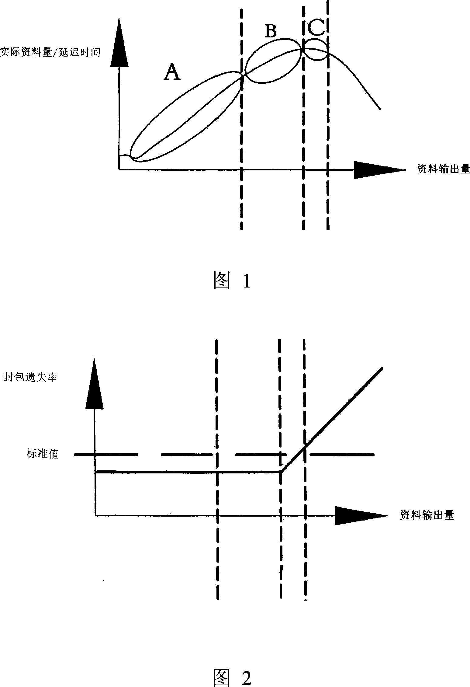
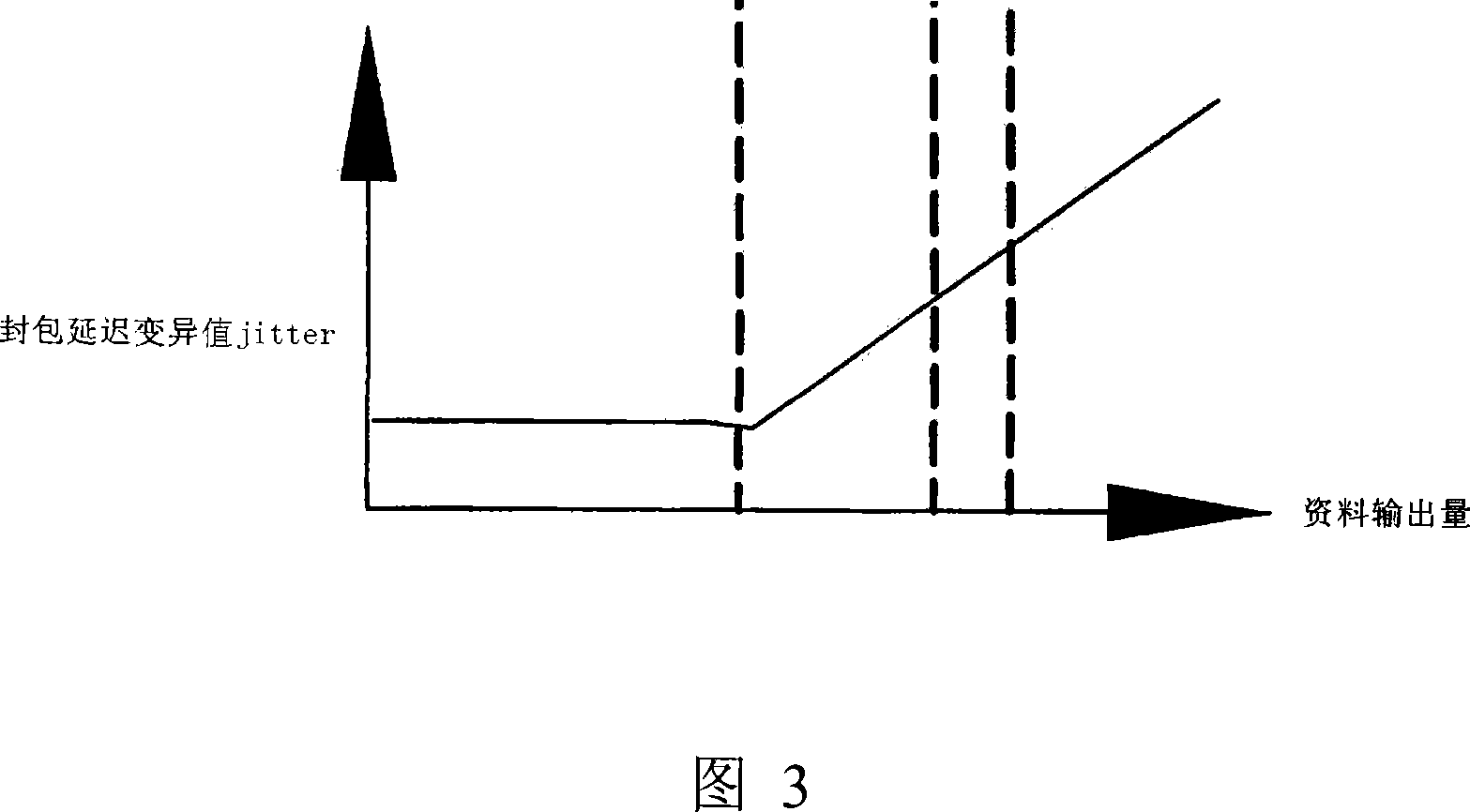
[0021] Please refer to Fig. 1 now, Fig. 1 is the actual data amount / delay time of the present invention and the coordinate diagram of data transmission volume, Fig. 2 is the coordinate diagram of packet loss rate and data transmission volume of the present invention and Fig. 3 is the packet delay variation value JITTER and the present invention Graph of data transfer volume. As shown in the figure, we divide a network bandwidth 10 (not shown in the figure) into three sections: a sufficient area A, an optimal bandwidth area B, and a congested area C. The ample area A represents that the bandwidth is still equivalent. The amount of data is sufficient, and the amount of data...


PUM


Abstract

The invention discloses a network monitor system, especially a monitor adjusting system for network bandwidth, which includes pocket loss rate and packet delay mutation value JITIER, and it is defined in control information of RTCP which accord with RFC 3550 standard, which correspond with rich region A, optimal bandwidth region B and congestion region C; when packet delay mutation value JITIER is rich region A when without obvious rising; when the packet delay mutation value JITIER starts to rising, but the packet loss rate without obvious variation, and it is the optimal bandwidth region B; when the packet delay mutation value JITIER and packet loss rate are rising, it is the congestion region C; and rich region A, optimal bandwidth region B and congestion region C are distinguished by the packet delay mutation value JITIER and packet loss rate,which can get the optimal bandwidth region B by positive prediction, and it can reduce the risk of lost, and improve the transmission quality of network.

Description

technical field [0001] The invention relates to a network monitoring system, in particular to a network bandwidth monitoring and adjusting system. Background technique [0002] In modern times with advanced technology, the network is like the nerves of the human body, connecting the reactions of various organs in the human body together. Because of this, packet loss is easy to occur during network transmission. There are mainly three types of network packet loss The first reason is: general packet loss, because the network is an unreliable transmission, so the packet may be lost during the transmission process, the normal probability of packet loss is about 1% to 5%, but it still needs to follow the network The ability of the node device, the higher the ability of the device is, the lower the relative loss probability is, conversely, the weaker the ability of the device is, the higher the packet loss rate is. The second type: Insufficient bandwidth. The network is like a wa...

Claims


Application Information

Patent Timeline
IPC IPC(8): H04L12/26H04L12/56
Inventor 杨理程
Owner AMROAD TECH
Features
  • R&D
  • Intellectual Property
  • Life Sciences
  • Materials
  • Tech Scout
  • Unparalleled Data Quality
  • Higher Quality Content
  • 60% Fewer Hallucinations
Learn More