Method for monitoring sensor function

A sensor and potential sensor technology, applied in the direction of instruments, scientific instruments, protection equipment, etc.

Inactive Publication Date: 2007-12-12
ENDRESS HAUSER CONDUCTA GESELLSCHAFT FUER MESS UND REGELTECHNIK MBH CO KG
View PDF1 Cites 14 Cited by
  • Summary
  • Abstract
  • Description
  • Claims
  • Application Information

AI Technical Summary

Problems solved by technology

[0004] Regardless of the remaining operating time, it is necessary to limit the measuring accuracy of the sensor over the entire operating time with as much certainty as possible

Method used


Image

  • Method for monitoring sensor function
  • Method for monitoring sensor function
  • Method for monitoring sensor function

Examples


Embodiment Construction

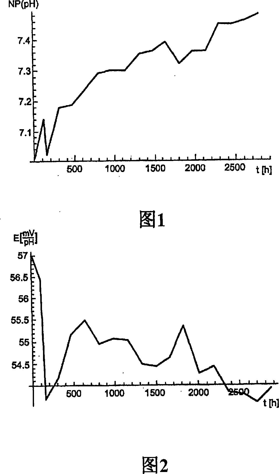
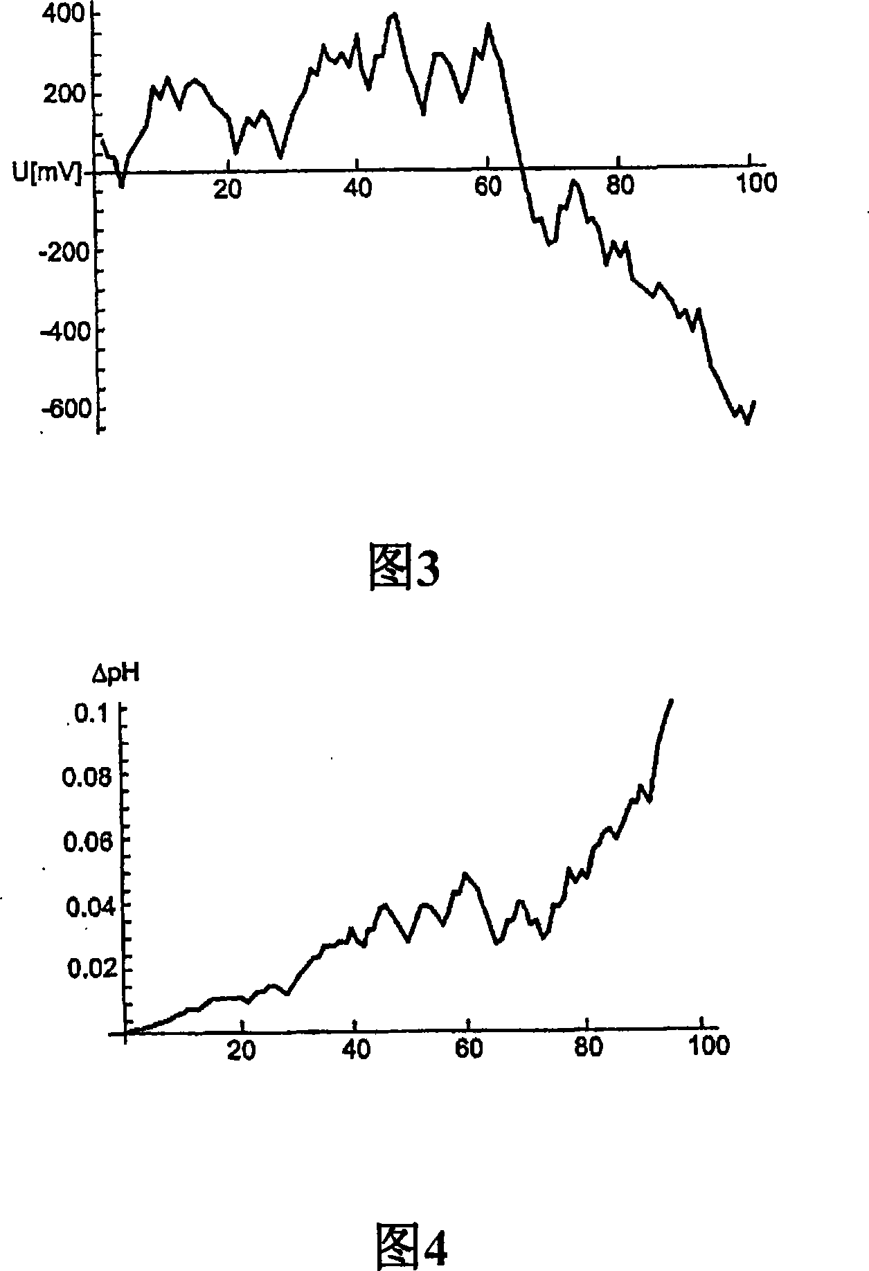
[0032] The graphs in Figures 1 to 4 relate to data from pH sensors. The basic characteristic quantities of the pH sensor are zero point NP and sensitivity E. These characteristic quantities must be calibrated at regular intervals to ensure the measurement accuracy of the measurement system.

[0033] Operating conditions affect changes in these characteristic quantities. The speed of change of these characteristic quantities reflects the operating conditions. Figures 1 and 2 show typical data for the time development of the zero point and sensitivity of a pH sensor. Each data point corresponds to a calibration value stored in the data set according to the present invention. Knowing the past time distribution, future changes can be inferred. In the simplest case, this is achieved by a smoothing function AE(t) for the sensitivity and ANP(t) for the zero point.

[0034] Figures 1 and 2 show the distribution of sensor data in 2820h. Determining the approximate development of ...


PUM


Abstract

A method for monitoring sensor functionality comprising the steps of: repeatedly obtaining a dataset comprising sensor-specific calibration data; storing the acquired dataset comprising sensor-specific calibration data; analyzing the temporal development of the calibration data based on the stored dataset; And the time until the next calibration or the time weighted by the load factor is determined at least from the temporal development of the calibration data. The resulting point in time or the determined time weighted by the load factor can be output in a suitable form, for example immediately after determination, so that the calibration can be planned in the long term and / or the resulting point in time or the determined time weighted by the load factor can be Stored as data or remaining time. By comparison with a time signal or by counting down the remaining time, a request signal can be output on the due date, which can optionally also have a desired lead time.

Description

technical field [0001] The invention relates to a method for monitoring the function of a sensor, in particular a potentiometric sensor. Background technique [0002] For process measuring points for process optimization or monitoring and observation of limit values, the most important requirements are simple operation, safety and reliability. Today, measuring points provide the operator with measured value information and, in some cases, additional information about the current condition of the system. In this case, for example, it is monitored whether a limit value is currently exceeded or whether a sensor-specific parameter (eg glass resistance of a pH sensor) is complied with. Thus, what is monitored is the current event. As far as plants are concerned, faults or interruptions cause costs that are much higher than the price of the sensors, and it is very important that faults at the measuring point be pre-empted as far as possible, where correct and guaranteed measured...

Claims


Application Information

Patent Timeline
Patent Type & Authority Applications(China)
IPC IPC(8): G01D3/08
CPCG01N27/4163G01D3/08
Inventor 托尔斯滕·佩希施泰因赫尔曼·施特劳布阿克塞尔·蒂申多夫
Owner ENDRESS HAUSER CONDUCTA GESELLSCHAFT FUER MESS UND REGELTECHNIK MBH CO KG
Why Eureka
Try Eureka