Dual bypass for piston-type flushometer

A flushing valve and piston technology, applied in the field of flushing valves, can solve the problems of increasing flushing volume, increasing operating costs, etc., and achieve the effects of reducing flushing volume, reducing travel distance, and simplifying assembly

Inactive Publication Date: 2007-12-19
SLOAN VALVE COMPANY
View PDF2 Cites 9 Cited by
  • Summary
  • Abstract
  • Description
  • Claims
  • Application Information

AI Technical Summary

Problems solved by technology

Greater water travel requires greater pressure to act on the piston and tends to increase flush volume, both of which increase operating costs

Method used


Image

  • Dual bypass for piston-type flushometer

Examples


Embodiment Construction

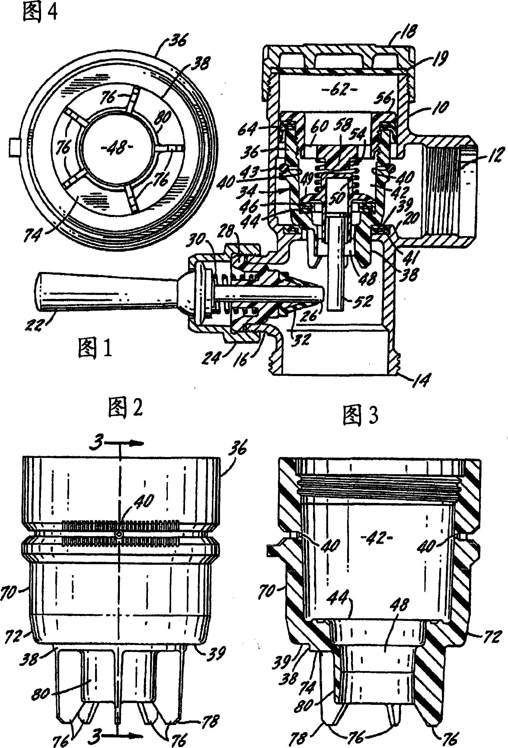
[0014] The piston of the present invention is conventionally used with flush valve assemblies for urinals or toilets. The flush valve piston is designed to control the flow of water through the flush valve in order to provide a specific amount of water for each flush operation, while the water passes through the flush valve at a high rate even when the water pressure is at the low end of the water pressure range commonly found in the United States. Although the present invention states that the desired water volume for each flush is 1.6 gallons or 6 liters, it should be understood that the size of the various components can be modified to provide a different water volume for each flush.

[0015] The flushing valve shown in the drawings has a generally hollow valve body 10 including an inlet connection portion 12, an outlet connection portion 14 and a handle connection portion 16. The top of the valve body is closed by a valve cover 18, and there may be a sealing element 19 between...


PUM


Abstract

A flushometer for use with urinals or water closets includes a hollow valve body having an inlet, an outlet, and a valve seat therebetween. There is a piston or diaphragm movable in the hollow valve body to a closing position on the valve seat to control flow through the valve. A pressure chamber is above the piston or diaphragm for holding it on the valve seat. The piston or diaphragm includes a plurality of bypass orifices to connect the inlet with the pressure chamber to provide fluid to move the piston or diaphragm to the closing position.

Description

Technical field [0001] The present invention generally relates to diaphragm or piston flush valves used in urinals, toilet bowls or the like. More specifically, the present invention relates to a flush valve having a plurality of bypass holes. Background technique [0002] Piston flushing valves with bypass holes are well known, as exemplified by the flushing valve shown in U.S. Patent No. 4,261,545, which is incorporated herein by reference. The diaphragm flush valve also has several bypass holes, as exemplified by the flush valve shown in U.S. Patent No. 6,616,119, which is incorporated herein by reference. The bypass hole provides inlet fluid pressure above the piston or diaphragm, which is used to close the piston assembly or diaphragm on the valve seat after flushing, and then keep the piston assembly or diaphragm on the valve seat. The bypass hole is machined to a certain size to allow a predetermined amount of fluid to flow through the flush valve before the valve is close...

Claims


Application Information

Patent Timeline
Patent Type & Authority Applications(China)
IPC IPC(8): E03D1/34
CPCF16K31/3835E03D3/04
Inventor D·J·卡罗尔P·A·施米特
Owner SLOAN VALVE COMPANY
Why Eureka
Try Eureka