Power supply circuit

A power supply circuit and circuit technology, which is applied in the direction of adjusting electrical variables, instruments, and converting irreversible AC power input into DC power output, etc., can solve the problems of large stress impact on the subsequent circuit and unstable input power of isolated high-frequency transformers, etc. Achieve the effect of reducing stress shock and improving product reliability

Inactive Publication Date: 2007-12-19
INNOCOM TECH SHENZHEN +1
View PDF0 Cites 1 Cited by
  • Summary
  • Abstract
  • Description
  • Claims
  • Application Information

AI Technical Summary

Problems solved by technology

[0006] In order to solve the problems in the prior art that the power supply circuit has a large stress impact on the subsequent circuit and the input power of the isolated high-frequency transformer is unstable, the present invention provides a power supply that has a small stress impact on the subsequent circuit and stabilizes the input power of the isolated high-frequency transformer. circuit

Method used


Image

  • Power supply circuit
  • Power supply circuit

Examples


Embodiment Construction

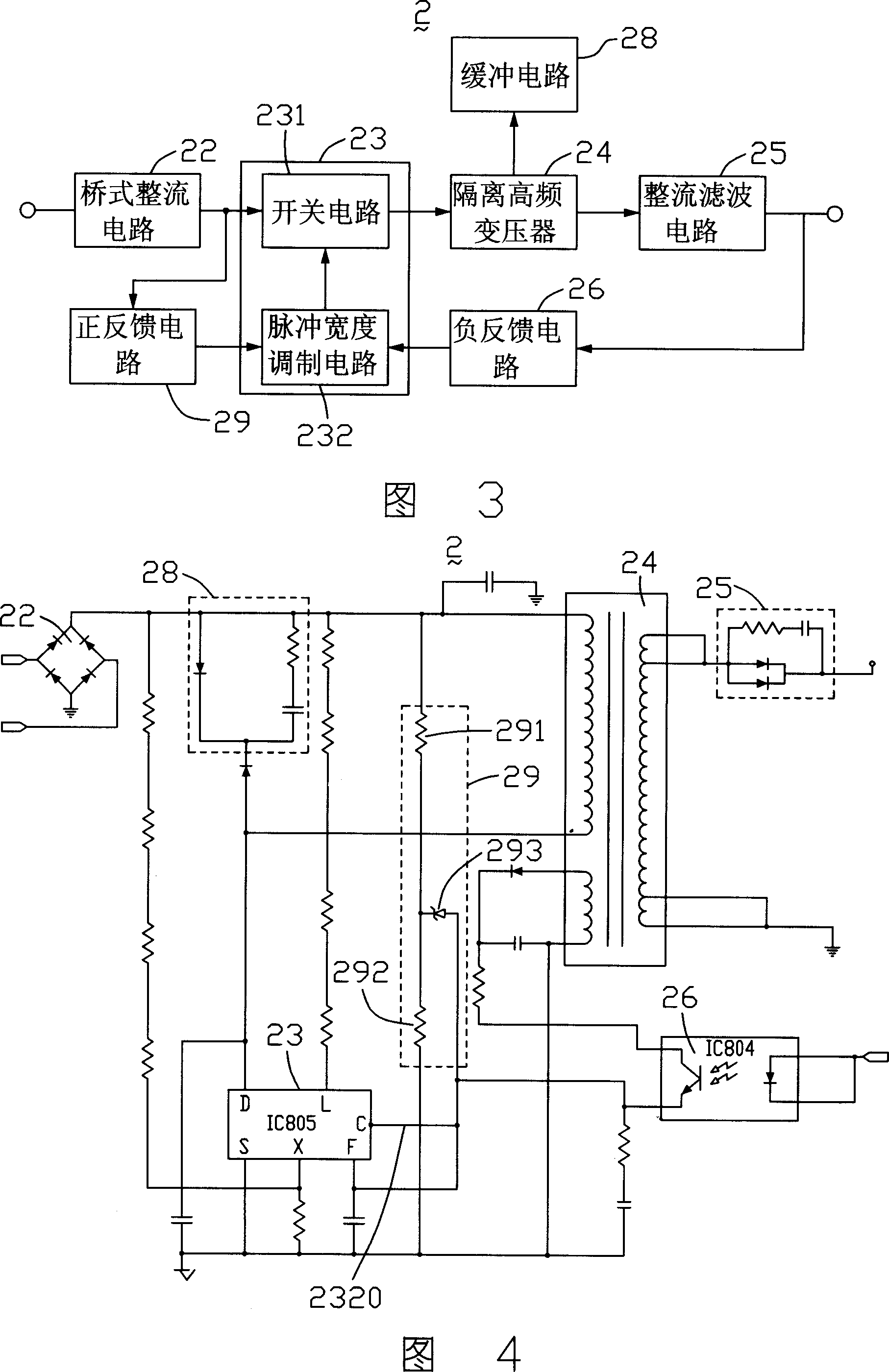
[0013] Please refer to FIG. 3 , which is a circuit block diagram of the power supply circuit of the liquid crystal display device of the present invention. The power supply circuit 2 includes a bridge rectifier circuit 22, a control circuit 23, an isolated high frequency transformer 24, a rectification filter circuit 25, a negative feedback circuit 26, a buffer circuit 28 and a positive feedback circuit 29, the control circuit 23 includes a switch circuit 231 and a pulse width modulation circuit 232 .

[0014] Please refer to FIG. 4 , which is a specific circuit structure diagram of the power supply circuit shown in FIG. 3 . Wherein, the control circuit 23 is implemented by an integrated circuit IC805, and the negative feedback circuit 26 is implemented by an optocoupler feedback device IC804. The integrated circuit IC805 has input overvoltage and undervoltage protection functions. The positive feedback circuit 29 includes a first resistor 291, a second resistor 292 and a Ze...


PUM


Abstract

A power supply circuit is prepared as forming control circuit by a switch circuit and a pulse width modulation circuit, converting outside AC voltage to be DC voltage by bridge rectification circuit, outputting said AC voltage through switch circuit and isolation high frequency transformer as well as rectification-filtering circuit, receiving AC voltage by direct feedback circuit and feeding back AC voltage to pulse width modulation circuit being used to control switched-on time of switch circuit according to received feedback signal.

Description

technical field [0001] The invention provides a power supply circuit, in particular to a power supply circuit applied to a liquid crystal display device. Background technique [0002] The power supply circuit of a liquid crystal display device generally adopts a flyback topology, and its AC input wide voltage (from 90V to 240V) design can simultaneously meet the requirements of users with different power supply specifications all over the world. Due to the large voltage span, it is very easy to cause a sudden increase and decrease of the input voltage due to the influence of the change of the power grid, resulting in unstable input power and a large stress impact on the secondary, reducing the safety of the product and the reliability of the device. Due to the instability of its power, it affects the stability of the power grid and does not meet the requirements of green environmental protection. [0003] Please refer to FIG. 1 , which is a circuit module diagram of a power...

Claims


Application Information

Patent Timeline
Patent Type & Authority Applications(China)
IPC IPC(8): G02F1/133H02M7/02G05F1/46
Inventor 肖华周通
Owner INNOCOM TECH SHENZHEN
Why Eureka
Try Eureka