A high-efficiency photovoltaic grid-connected inverter with active auxiliary ripple suppression and its control method

A ripple suppression and high-efficiency technology, applied in the field of high-efficiency photovoltaic grid-connected inverters and their control, can solve the problems of short life of electrolytic capacitors, increased maintenance costs, and limited efficiency

Active Publication Date: 2020-05-08
NANJING UNIV OF AERONAUTICS & ASTRONAUTICS
View PDF5 Cites 0 Cited by
  • Summary
  • Abstract
  • Description
  • Claims
  • Application Information

AI Technical Summary

Problems solved by technology

Generally speaking, it is the easiest way to smooth the input power by connecting a large-capacity electrolytic capacitor in parallel on the DC side, but the life of the electrolytic capacitor is very short, much lower than the life of the solar photovoltaic panel, and increases the maintenance cost
In the circuit, the LC resonant branch whose resonant frequency is twice the grid frequency can also suppress the power ripple and reduce the capacitance value at the same time, but the inductance value and capacitance value required by this method are still relatively large. Reduce system power density
All in all, the method of using passive devices to suppress the power ripple on the input side caused by the grid-connected side of the inverter has the disadvantages of large size, low reliability, and limited efficiency.

Method used


Image

  • A high-efficiency photovoltaic grid-connected inverter with active auxiliary ripple suppression and its control method
  • A high-efficiency photovoltaic grid-connected inverter with active auxiliary ripple suppression and its control method
  • A high-efficiency photovoltaic grid-connected inverter with active auxiliary ripple suppression and its control method

Examples


Embodiment Construction

[0026] Below in conjunction with accompanying drawing, the technical scheme of invention is described in detail:

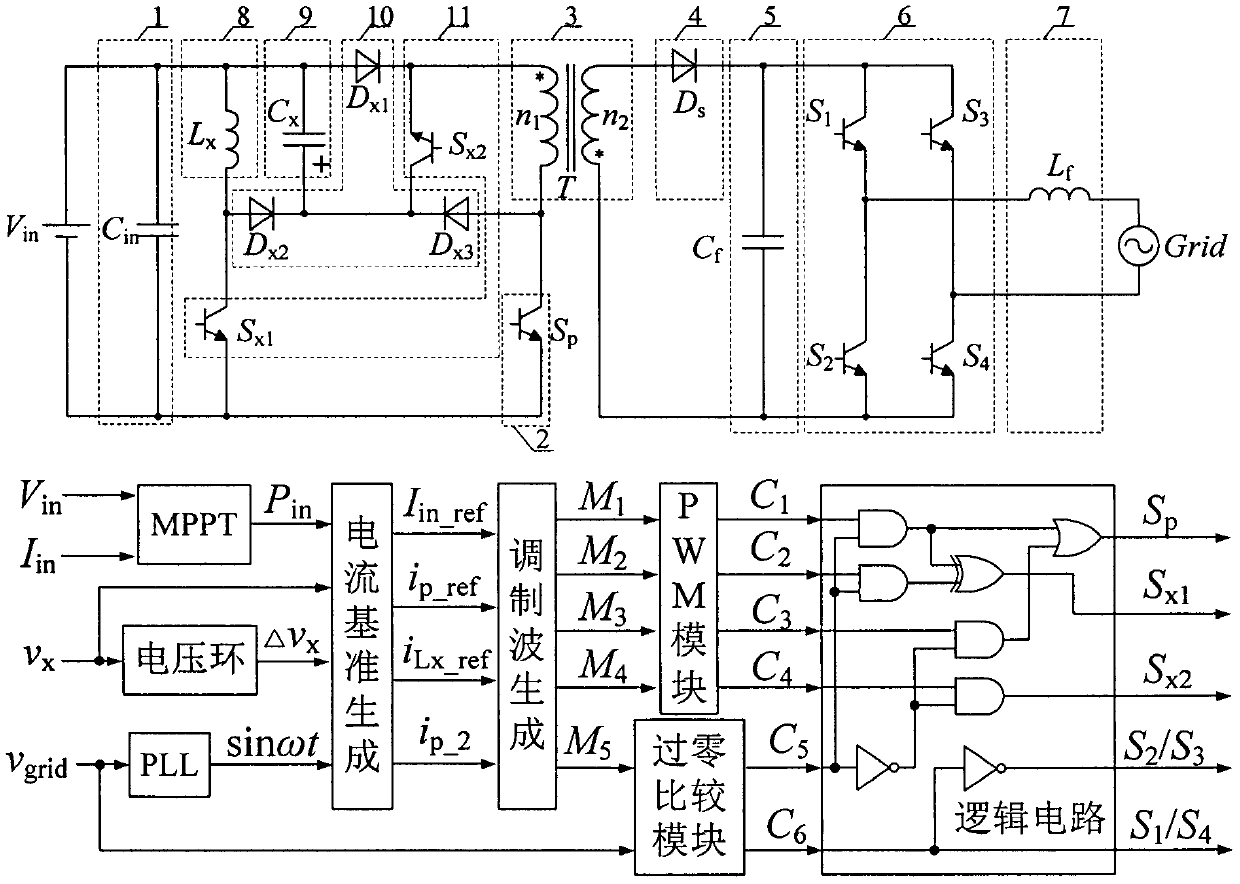
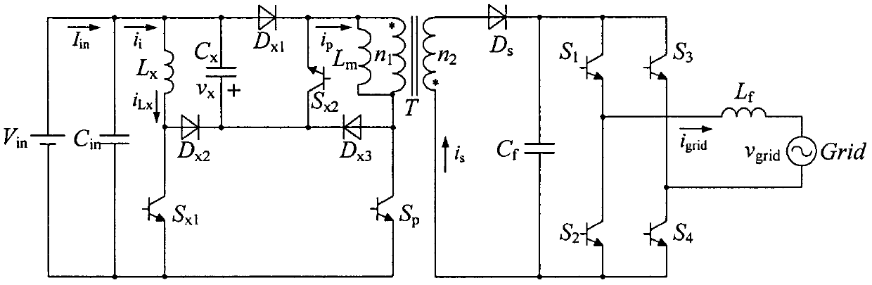
[0027] attached figure 1 What is shown is a schematic structural diagram of a main circuit of a high-efficiency photovoltaic grid-connected inverter with active auxiliary ripple suppression and its control method. The main circuit of a high-efficiency photovoltaic grid-connected inverter with active auxiliary ripple suppression is powered by a DC power supply V in , Input capacitor 1, primary switch tube 2, isolation transformer 3, cut-off diode 4, filter capacitor 5, polarity inversion inverter bridge 6, filter inductor 7, power grid, auxiliary inductor 8, decoupling capacitor 9, auxiliary diode 10 and auxiliary switch tube 11. C in is the input capacitance, T is the isolation transformer, S p is the primary switch tube, S x1 , S x2 is the auxiliary switch tube, L x is the auxiliary inductance, D x1 ~D x3 is the auxiliary diode, C x is the decoupling ca...


PUM


Abstract

The invention discloses a high-efficiency photovoltaic grid-connected inverter for active auxiliary ripple suppression, and a control method thereof. The main circuit typology of the high-efficiency photovoltaic grid-connected inverter comprises a DC power supply, an input capacitor, a primary side switching tube, an auxiliary inductor, a decoupling capacitor, an auxiliary switching tube, an auxiliary diode, an isolation transformer, a pick-off diode, a filtering circuit, a polarity-reversal inverter bridge, a filtering inductor and a power grid. The control method comprises the steps that input voltage and current sampling values are subjected to MPPT to obtain the maximum DC input power, a power grid voltage sampling value is input to PLL to obtain a sine wave having the same frequency and the same phase as the power grid voltage sampling value, and switching tube control signals are finally obtained by means of a current reference generation module, a modulated wave generation module, a PWM module, a zero-crossing comparison module and a logic circuit. According to the high-efficiency photovoltaic grid-connected inverter, an active auxiliary unit composed of the auxiliary inductor, the auxiliary switching tube, the auxiliary diode and the decoupling capacitor is added to the primary side of the transformer, and the dual functions of secondary ripple suppression at the DC input side and grid connection are achieved.

Description

technical field [0001] The invention relates to a high-efficiency photovoltaic grid-connected inverter with active auxiliary ripple suppression and a control method thereof, which belongs to a miniature grid-connected inverter, and uses an added active auxiliary unit to realize current neutralization at the input side of a DC power supply. secondary ripple suppression. Background technique [0002] Due to the global energy crisis and environmental pollution, photovoltaic power generation has attracted people's attention due to its clean and sustainable advantages, which has prompted the rapid development of the photovoltaic industry. Photovoltaic panels use maximum power tracking technology to achieve their maximum power stable output, and the power pulsation of twice the grid frequency contained in the output power of the grid-connected side will be transmitted to the input side of the inverter. If the power pulsation is not decoupled, It will affect the maximum power trac...

Claims


Application Information

Patent Timeline
Patent Type & Authority Patents(China)
IPC IPC(8): H02J3/38H02M1/14H02M3/335H02M7/537
CPCH02J3/383H02M1/14H02M3/3353H02M7/537Y02E10/56
Inventor 陈仲袁涛李梦南章修齐
Owner NANJING UNIV OF AERONAUTICS & ASTRONAUTICS
Why Eureka
Try Eureka