
Single-phase photovoltaic grid-connected inverter based on ripple power transfer and modulating control method

A technology of power transfer and modulation method, which is applied in the direction of output power conversion device, conversion of AC power input to DC power output, photovoltaic power generation, etc., which can solve capacitor damage, photovoltaic cell operating point deviation from maximum power point, and reduce photovoltaic array efficiency And other issues

Inactive Publication Date: 2014-03-26
CENT SOUTH UNIV
View PDF1 Cites 18 Cited by
  • Summary
  • Abstract
  • Description
  • Claims
  • Application Information

AI Technical Summary

Problems solved by technology

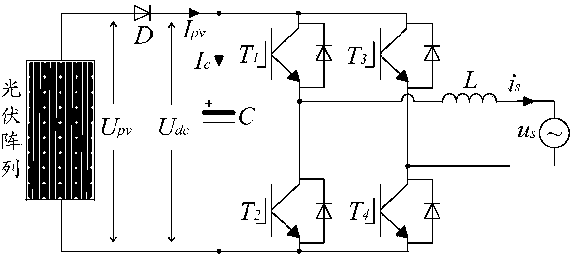
[0002] The DC voltage ripple of the photovoltaic system will cause the following problems: 1) The ripple voltage will cause the temperature of the capacitor to rise, which is the most important factor leading to capacitor damage; 2) The DC voltage ripple will cause the voltage outer loop control to contain harmonic components, These harmonic components not only cannot maintain the stability of the DC voltage, but also cause low-frequency harmonic disturbances in the reference signal of the current inner loop; 3) For the flow control loop of the photovoltaic system, even if the low-frequency disturbance in the reference current is suppressed, at the modulation level, the DC side The impact of voltage ripple on current tracking control performance cannot be ignored
If the capacitance value is too small, the voltage fluctuation on the DC side will be large, which will cause the electrolytic capacitor to withstand a large ripple voltage, causing the capacitor to heat up, which will shorten the life of the electrolytic capacitor
Choosing a capacitor with a larger capacitance can effectively suppress the size of the ripple, but a larger capacitance will result in slower tracking of the maximum energy output point of the photovoltaic cell, and at the same time the volume and cost of the capacitor will increase
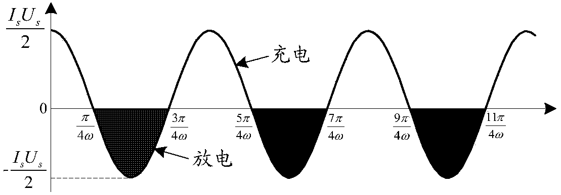
[0023] 2. DC voltage ripple analysis of single-phase bridge photovoltaic inverter under non-ideal conditions
[0042] 3. Influence of secondary power disturbance on photovoltaic grid-connected system
[0043] The DC voltage ripple of the photovoltaic system will cause the following problems: 1) The ripple voltage will cause the temperature of the capacitor to rise, which is the most important factor leading to capacitor damage; 2) The DC voltage ripple will cause the voltage outer loop control to contain harmonic components, These harmonic components not only cannot maintain the stability of the DC voltage, but also cause low-frequency harmonic disturbances in the reference signal of the current inner loop; 3) For the current control loop of the photovoltaic system, even if the low-frequency disturbance in the reference current is suppressed, at the modulation level, the DC side The impact of voltage ripple on current tracking control performance cannot be ignored
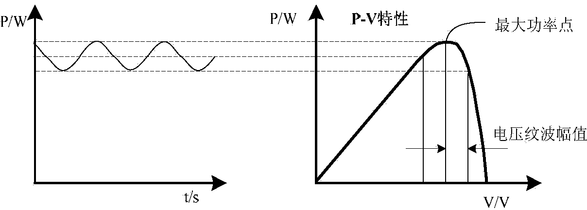
[0053] It can be obtained from the above formula that when the photovoltaic array operates at the maximum power point, the voltage ripple will cause the output power of the photovoltaic array to be lower than the maximum power point, and the power waveform is as follows image 3 shown
[0054] from image 3 It can be seen that the ripple of the DC side voltage causes the operating point of the photovoltaic cell to deviate from the maximum power point, and the average output power decreases
The AC component of the instantaneous power output by the photovoltaic grid-connected inverter is unavoidable. This ripple power not only affects the efficiency of photovoltaic cells, but also reduces the service life of photovoltaic cells
[0055] 4. The influence of the secondary power disturbance on the command current of the inverter
From formula (27), it can be seen that the ripple voltage on the DC side not only causes the voltage on the AC side to contain the third harmonic, but also shifts the amplitude and phase of the fundamental frequency component on the AC side
[0081] The above analysis shows that the ripple power of the single-phase photovoltaic inverter leads to 1) the ripple voltage on the DC side capacitor, which will not only cause the temperature of the capacitor to rise, but also reduce the efficiency of the photovoltaic array; 2) the photovoltaic inverter The reference signal of the AC output current of the converter has low-frequency harmonic disturbances mainly of the third order; 3) The ripple of the DC side voltage is introduced into the output current during the modulation process, which not only includes harmonics, but also shifts the amplitude and phase of the fundamental wave

Method used


Image

  • Single-phase photovoltaic grid-connected inverter based on ripple power transfer and modulating control method
  • Single-phase photovoltaic grid-connected inverter based on ripple power transfer and modulating control method
  • Single-phase photovoltaic grid-connected inverter based on ripple power transfer and modulating control method

Examples


Embodiment 1

[0140] Improved topology of photovoltaic inverter based on decoupling circuit

[0141] Based on the above analysis of the secondary power disturbance, referring to the ripple power transfer circuit of the single-phase rectifier circuit, the Figure 7 The improved topology is shown. This improved photovoltaic inverter topology, on the basis of the traditional full bridge, adds a secondary power decoupling circuit, and the decoupling circuit is composed of a power switch T5, a diode D2 and an energy storage inductor L2.

[0142] Depend on Figure 7 Visible inductance energy storage inductance L 2 The current is only in the positive direction, then the energy storage inductance L 2 current i L can be assumed to be

[0143] i L = I L |cos(ωt-α)| (28)

[0144] where I L is the current peak value, and α is the lag angle.

[0145] Inductance L 2 energy E L2 and power P L2 can be expressed as

[0146] E L 2 ...


PUM


Abstract

The invention discloses a single-phase photovoltaic grid-connected inverter based on ripple power transfer and a modulating control method. Based on the thought of 'energy transfer', second power of a direct-current side capacitor is transferred to an inductor element by adding one degree of freedom of control into the inverter, and a novel inverter topology structure based on a ripple power transfer circuit is constructed. By combining a grid-connected current control link, a modulation method and system control strategy of the new topology is given. Analysis proves that by the novel single-phase single-stage inverter, second power disturbance can be effectively controlled, second ripple components are inhibited, photovoltaic system efficiency and grid-connected current quality are improved, alternating current in a power inductor is guaranteed, and influence on system reliability and efficiency due to direct-current bias current of the inductor is avoided. Simulation and experiment results verify reasonability and effectiveness of the novel inverter and the modulating control strategy.

Description

technical field [0001] The invention relates to a single-phase photovoltaic grid-connected inverter based on ripple power transfer and a modulation control method. Background technique [0002] The DC voltage ripple of the photovoltaic system will cause the following problems: 1) The ripple voltage will cause the temperature of the capacitor to rise, which is the most important factor leading to capacitor damage; 2) The DC voltage ripple will cause the voltage outer loop control to contain harmonic components, These harmonic components not only cannot maintain the stability of the DC voltage, but also cause low-frequency harmonic disturbances in the reference signal of the current inner loop; 3) For the flow control loop of the photovoltaic system, even if the low-frequency disturbance in the reference current is suppressed, at the modulation level, the DC side The impact of voltage ripple on the performance of current tracking control cannot be ignored. [0003] 1. Analysi...

Claims


Application Information

Patent Timeline
IPC IPC(8): H02M7/5387
CPCY02E10/56
Inventor 于晶荣陈莎程美红张雪煜王一军段娟凤郑玉芳章文远涂睿徐勇
Owner CENT SOUTH UNIV
Learn More