Device for elevator

A technology for elevators and stop devices, applied in transportation and packaging, elevators, etc., can solve the problems of slow braking force and time-consuming

Inactive Publication Date: 2007-12-19
MITSUBISHI ELECTRIC CORP
View PDF2 Cites 18 Cited by
  • Summary
  • Abstract
  • Description
  • Claims
  • Application Information

AI Technical Summary

Problems solved by technology

[0006] However, in the above-mentioned conventional brake device and brake control device, both of the basic emergency braking operation and the control of the b

Method used


Image

  • Device for elevator
  • Device for elevator
  • Device for elevator

Examples


Example Embodiment

[0015] Hereinafter, preferred embodiments of the present invention will be described with reference to the drawings.
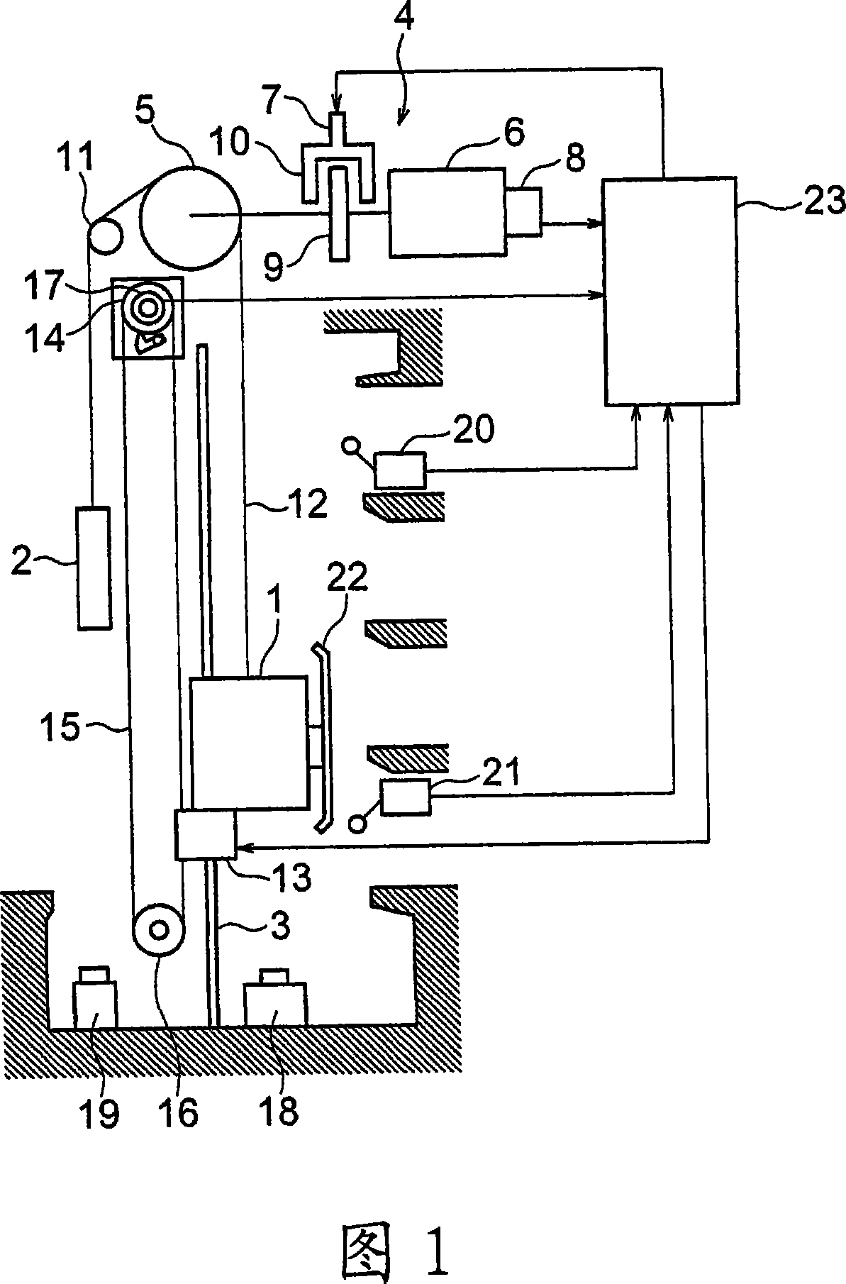
[0016] Figure 1 is a configuration diagram showing an elevator apparatus according to Embodiment 1 of the present invention. The elevator car 1 and the counterweight 2 as an elevator body are raised and lowered in the hoistway. A car guide rail 3 that guides the lifting of the car 1 and a counterweight guide rail (not shown) that guides the lifting of the counterweight 2 are provided in the hoistway.

[0017] In the upper part of the hoistway, a hoist 4 for raising and lowering the car 1 and the counterweight 2 is provided. The winch 4 has a drive pulley 5, a motor 6 that rotates the drive pulley 5, a winch brake 7 that brakes the rotation of the drive pulley 5, and a pulley speed detection that detects the rotation speed of the drive pulley 5 (the rotation speed of the rotating shaft of the motor 6)器8. As the pulley speed detector 8, for example, a motor encoder ...


PUM


Abstract

In an elevator apparatus, a brake control device has a first brake control portion, a second brake control portion, and a third brake control portion. The first brake control portion operates a hoisting machine brake to stop a ascending/descending body as an emergency measure when an abnormality is detected. The second brake control portion reduces a braking force of the hoisting machine brake when a deceleration of the ascending/descending body becomes equal to or higher than a predetermined value during an emergency braking operation of the hoisting machine brake. The third brake control portion monitors a slip speed of a main rope with respect to a drive sheave during emergency braking operation of the hoisting machine brake, and reduces a braking force of the hoisting machine brake when the slip speed of the main rope becomes equal to or higher than a predetermined value.

Description

technical field [0001] The present invention relates to an elevator apparatus having a brake control device for controlling the brake of a hoisting machine. Background technique [0002] In a conventional elevator brake device, during emergency braking, the braking force of the electromagnetic brake is controlled based on a deceleration command value and a speed signal so that the deceleration of the car becomes a predetermined value (for example, refer to Patent Document 1). [0003] In addition, in the conventional elevator braking control device, when the rope sliding speed obtained as the difference between the pulley speed and the car speed during emergency braking becomes more than a predetermined value, the application of the braking force is weaker than that of the full braking force. The braking force (for example, refer to Patent Document 2). [0004] Patent Document 1: Japanese Patent Application Laid-Open No. 7-157211 [0005] Patent Document 2: Japanese Patent...

Claims


Application Information

Patent Timeline
IPC IPC(8): B66B1/32B66B5/02B66B5/22
CPCB66B5/02B66B1/32B66B5/22
Inventor 上田隆美柴田益诚冈本健一高桥理
Owner MITSUBISHI ELECTRIC CORP
Why Eureka
Try Eureka