Apparatus for escaping with one's life from storied buildings, and escaping method
An escape method and escape device technology, applied in life-saving equipment, building rescue and other directions, can solve problems such as insecurity, guide wheel sticking, hidden safety hazards, etc., to improve efficiency and reliability, unique structural design, braking good effect
- Summary
- Abstract
- Description
- Claims
- Application Information
AI Technical Summary
Problems solved by technology
Method used
Image
Examples
Embodiment 1
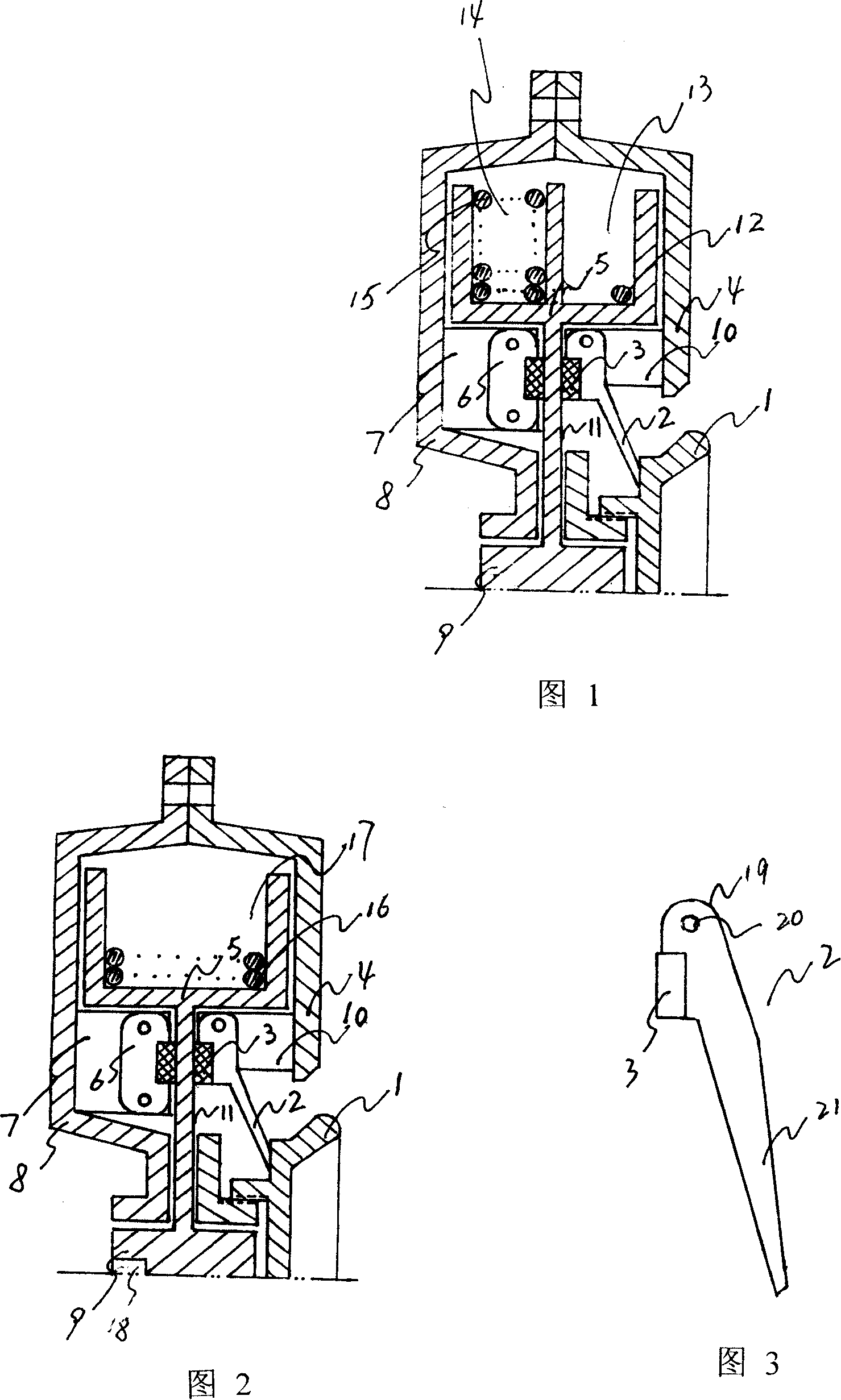
[0013] Embodiment 1: with reference to accompanying drawing 1 and 3. Building escape device, the wheel surface of runner 5 is double-groove structure 13 and 14 and is positioned in the space that outer hub 8 and 4 constitute on the left and right, runner 5 adopts prior art processing and forming or die-casting molding or injection molding. A rope 15 in the two ropes is wound in a groove 14 of the runner, and one end of the other rope 12 is connected with another groove 13 of the runner, and its rope 12 is positioned outside the runner groove, and the rope 12 and 15 can be steel wire rope, also can be nylon rope, etc. The wheel shaft 9 of the runner is located in the axle sleeve formed by the left and right outer hubs, the static brake pad assembly and the dynamic brake pad assembly are respectively matched with the wheel wall 11 of the runner 5 and are used to brake the runner 9, the handwheel 1 is screwed on the sleeve formed by the outer hub and is used to control the braki...
Embodiment 2
[0014]Embodiment 2: On the basis of Embodiment 1, using the escape method of the building escape device, the building escape device is hung on the wall of the building or fixed on other fixtures, and the hand wheel is manually tightened so that the brake pad and the runner The wall of the wheel forms a detent engagement, that is, the runner does not turn. The escaper connects the rope wrapped in a groove of the runner through the locking sleeve or directly binds the rope around the waist. At this time, the escaper hangs outside the building and prepares to escape. The moving plate and the wheel wall of the runner form a braking slide, and the descending speed of the escapee is controlled by the hand wheel. When the escaper descends, the rope located outside the other groove of the runner is wound on the other side with the rotation of the runner. In the groove, when the escapee safely descends to the ground and untie the rope, another escapee upstairs will tie the rope wrapped...
Embodiment 3
[0015] Embodiment 3: with reference to accompanying drawing 2 and 3. In the building escape device, the runner 5 is located in the space formed by the left and right outer hubs 8 and 4 and the wheel shaft 9 of the runner is located in the axle sleeve formed by the left and right outer hubs. There is crank jack 18 and matches with crank, that is to say, crank rotates, and drive axle 9 rotates, and rotating shaft drives wheel groove and rotates, and wheel groove rotates and the rope that has released is taken back in the wheel groove. The static brake pad assembly is composed of a brake pad 3, a brake pad insert 6 and a brake pad fixing frame 7, and the brake pad fixing frame 7 is fixed in the left outer hub (left housing) 8 or the right outer hub 4 ( Right housing), the brake pad insert 6 is fixed on the brake pad holder 7, the brake pad 3 is embedded on the brake pad insert 6 and the braking surface of the brake pad 3 is in contact with the wheel wall 11 of the runner. match....
PUM
 Abstract
Description
Claims
Application Information
 - R&D
- Intellectual Property
- Life Sciences
- Materials
- Tech Scout
- Unparalleled Data Quality
- Higher Quality Content
- 60% Fewer Hallucinations
Browse by: Latest US Patents, China's latest patents, Technical Efficacy Thesaurus, Application Domain, Technology Topic, Popular Technical Reports.
© 2025 PatSnap. All rights reserved.Legal|Privacy policy|Modern Slavery Act Transparency Statement|Sitemap|About US| Contact US: help@patsnap.com

