Water mixer with single baffler capable of adjusting proportion for mixing bidirectional water in heating circulation
A plate water mixer, the technology in operation, applied in the field of water mixer, can solve the problems that no adjustment can be made, the pressure equalizing tank can not adjust the water supply temperature, etc.
- Summary
- Abstract
- Description
- Claims
- Application Information
AI Technical Summary
Problems solved by technology
Method used
Image

Examples
specific Embodiment approach 1
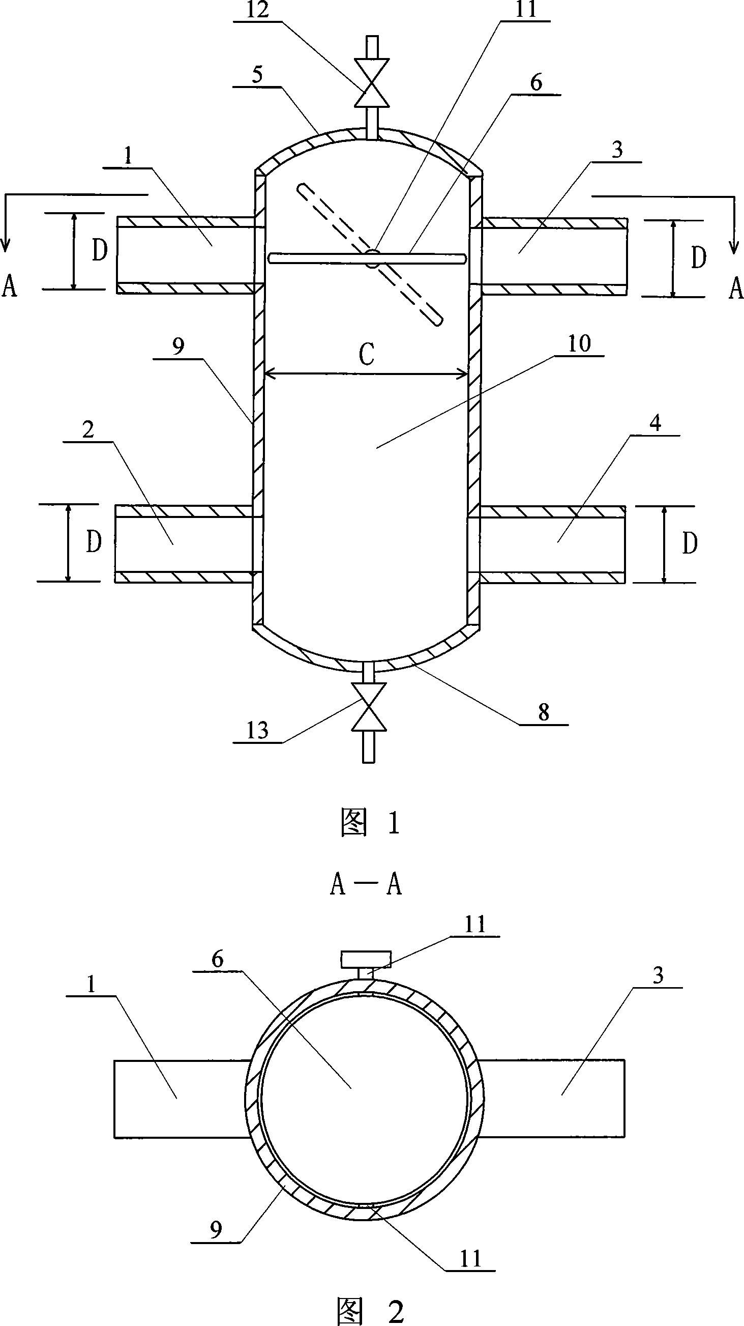
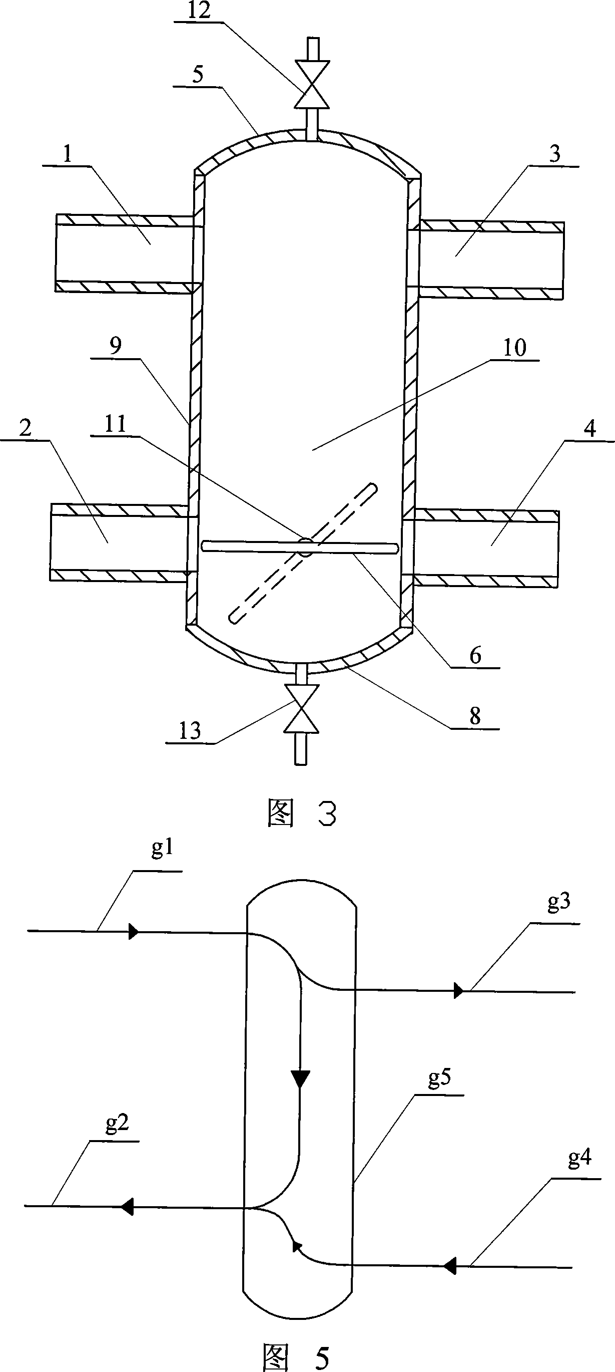
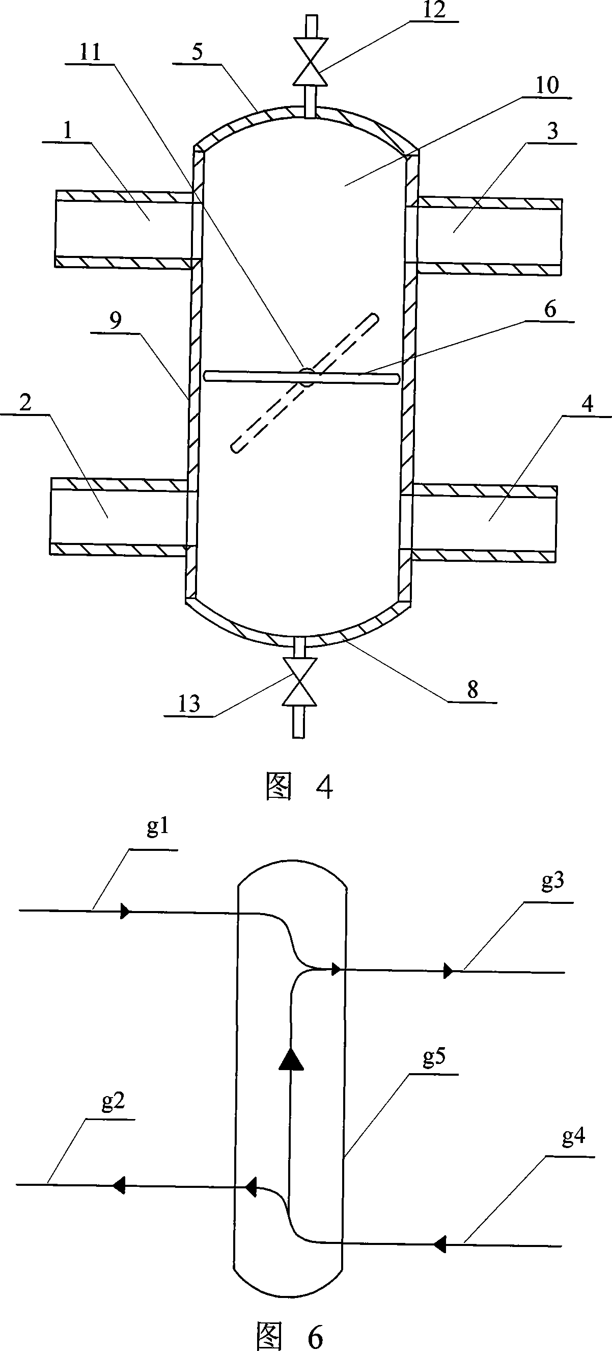
[0005] Specific embodiment 1: (see Fig. 1, Fig. 2) this embodiment consists of heating network water supply pipe interface 1, heating network return pipe interface 2, user water supply pipe interface 3, user return water pipe interface 4, upper ball crown 5, diversion Board 6, lower spherical crown 8, pipe body 9 and rotating shaft 11, upper spherical crown 5 is fixedly connected to the upper end of pipe body 9, lower spherical crown 8 is fixedly connected to the lower end of pipe body 9, and the heating network water supply pipe interface 1 is connected to the user The water supply pipe interface 3 is respectively fixed on the two side walls of the pipe body 9, and the heat network return pipe interface 2 and the user return pipe interface 4 are respectively fixed on the pipe body 9 on the lower side of the heat network water supply pipe interface 1 and the user water supply pipe interface 3. On both side walls, the deflector 6 is arranged in the cavity 10 of the tube body 9 ,...
specific Embodiment approach 2
[0006] Embodiment 2: (see FIG. 1 and FIG. 2 ) In this embodiment, the diameter of the deflector 6 is 0.5-10 mm smaller than the inner diameter of the pipe body 9 . Others are the same as in the first embodiment.
[0007] In order to achieve the best splitting effect, the difference between the size (diameter) of the deflector and the inner diameter of the pipe body should be as small as possible. When the deflector is in the horizontal position, the edge of the deflector should be as close as possible to the inner wall of the cylinder without affecting the flexibility of rotation of the deflector.
specific Embodiment approach 3
[0008] Specific embodiment three: (see Fig. 1, Fig. 2) the height of the heating network water supply pipe interface 1 and the user water supply pipe interface 3 in this embodiment is the same, and the height of the heating network return pipe interface 2 is the same as the user return water pipe interface 4. The water supply and return water connections of the pressure equalizing tank are staggered and cannot be at the same height, which increases the length of the pressure equalizing tank virtually and makes the space occupied by the pressure equalizing tank relatively large. This embodiment aims at these shortcomings of the existing water mixing device, so that the water in the hot water pipe network and the user side can be mixed effectively, satisfying the needs of the hot water users to adjust the temperature, and reducing the occupied space of the water mixing device as much as possible. Others are the same as in the second embodiment.
PUM
 Abstract
Description
Claims
Application Information
 - R&D
- Intellectual Property
- Life Sciences
- Materials
- Tech Scout
- Unparalleled Data Quality
- Higher Quality Content
- 60% Fewer Hallucinations
Browse by: Latest US Patents, China's latest patents, Technical Efficacy Thesaurus, Application Domain, Technology Topic, Popular Technical Reports.
© 2025 PatSnap. All rights reserved.Legal|Privacy policy|Modern Slavery Act Transparency Statement|Sitemap|About US| Contact US: help@patsnap.com